
|
|
Forum Index : Microcontroller and PC projects : Sonoff POWR2, Tasmota, mqtt, PiZW, bash power logging
| Page 1 of 2 |
|||||
| Author | Message | ||||
| lizby Guru Joined: 17/05/2016 Location: United StatesPosts: 3784 |
I've been wanting to log activity of my shallow well water pump, which typically comes on 12-20 times a day with normal usage. The Sonoff POWR2 device looked like a good solution, capable of supplying 15A and with a good bit of telemetry available over wifi with an ESP8266 module. Searching found that replacing the Sonoff firmware with Tasmota would enable me to receive both on and off times, and power usage. The device has through-hole solder points for 3V3, Tx, Rx, and 0V, and they are easy to solder, but I just used a CH341 usb/ttl-serial module connected to long pin headers poked in--the weight of the CH341 was sufficient to maintain a good connection for flashing. I followed this site for flashing: Tasmotize That link also describes configuring the module, the wifi, and the mqtt. The web gui only allows certain types of configuration. More is available using the console accessed with the web gui. I used that to set a fixed IP ("IPAddress1 192.168.98.175"), to set the time zone and to send the mqtt telemetry information when the power draw exceeded a threshhold, and again when it dropped below a threshhold ("PowerHigh 15") and ("PowerLow 9"). The extensive set of console commands is here. I set an mqtt topic of "pump" The flashing link went on to use node-red to process the mqtt message. Some months ago I had set up some node-red tests on a headless pi Zero W which is my utility device for testing network-related ideas. When I looked at what I had done, I didn't have a clue what all those nifty symbols hid. Rather than relearn what I'd soon forget again, I thought I'd try to figure out how to do it with a program, since I understand programs. The pi has the Mosquitto mqtt broker program. Installing it also includes mosquitto_sub which allows you to view messages on given topics. But I don't very well understand Bash--I have to look up everything, often multiple times, and especially things like "$", "[", "{", "(", "`" and their different usages. It was painful, but I think I'll be able to understand it when I come back at a later time. I've been logging things about the house for 15+ years, with TCP messages going to an accumulator and backup accumulator in the form of "ID data1 data2 data3 timestamp", where ID is a capital letter, timestamp is in the form of "YYMMDDhhmmss" and data2 and data3 are frequently 0: "A 23 0 0 210818081648" means it was 23C in the bedroom at 8:16 this morning. I've given the POWR2 an ID of "K", with data1 being 1 for "pump on" and 0 for "pump off", data2 being 0 for the "on" message and the number of power units consumed for the "off" message, and data3 being the total power units from the time the device powered up. The mqtt telemetry message is json-formated like this: {\"Time\":\"2021-08-17T14:00:12\",\"ENERGY\":{\"TotalStartTime\":\"2021-08-08T17:48:43\",\"Total\":0.695,\"Yesterday\":0.021,\"Today\":0.172,\"Power\":6,\"ApparentPower\":6,\"ReactivePower\":0,\"Factor\":1.00,\"Voltage\":119,\"Current\":0.051}} The items of interest to me are "Time" and "ENERGY\Total" and "ENERGY\Power" (Power, if non-zero, means the pump has started; if "0", it has stopped.) Here's the Bash code: #!/bin/bash lastwatts=0 mosquitto_sub -u myUsername -P myPassword -t pump/SENSOR 2>/dev/null | while read msg; do t=$(echo "$msg" | jq .Time ) pwr=$(echo "$msg" | jq .ENERGY.Power ) watts=$(echo "$msg" | jq .ENERGY.Total ) tm=${t:3:2}${t:6:2}${t:9:2}${t:12:2}${t:15:2}${t:18:2} if [ "$pwr" == "0" ] ; then used=`/usr/bin/awk "BEGIN {print $watts*1000-$lastwatts*1000}"` else lastwatts=$watts pwr="1" used="0" fi echo "K $pwr $used $watts $tm" echo "K $pwr $used $watts $tm" | nc 192.168.2.70 8086 & echo "K $pwr $used $watts $tm" | nc 192.168.2.65 8086 & sleep 1s ; kill `pidof nc` done The "mosquitto_sub" command pipes into the "read" command, and then I break out the variables of interest using the jq JSON parser and build the timestamp. For "off" messages, I calculate the power-units used (times 1000). I'm not certain, but I think this is watts, so data2 would be milliwatts. This is a "do forever" loop. The echo commands which are piped to nc (netcat) send the TCP messages to my two accumulating TCP listeners. I get ON/OFF pairs like this logged: K 1 0 0.777 210818100802 K 0 31 0.808 210818100939 K 1 0 0.808 210818101016 K 0 425 1.233 210818102905 With bash, I'm strictly copy, paste, modify, fail, and experiment until I get what I want, so there is probably a more elegant way to do it. Perhaps a Linux guru like JohnS would have better ideas. So far, this is just proof of concept (I'm turning on a heater to simulate the water pump). Still to come is plugging the water pump into the cord with the POWR2 on it, and then integrating it with an AIMS auto-transfer switch inverter plus battery to enable the water pump to continue to run during a power outage. ~ Edited 2021-08-19 00:44 by lizby PicoMite, Armmite F4, SensorKits, MMBasic Hardware, Games, etc. on FOTS |
||||
| Plasmamac Guru Joined: 31/01/2019 Location: GermanyPosts: 620 |
Can't recommend the sonoff for this high load . It cant handle even < 10 A over a Month. Gtx Plasma |
||||
| lizby Guru Joined: 17/05/2016 Location: United StatesPosts: 3784 |
Are you talking about the 10A sonoff or the POWR2, which claims to be good for 16A? And in any case, I'm not sure how you can make a recommendation like this when you don't know the power usage or the duty cycle of my water pump. It's a 1/2hp 120V motor, and runs 12-20 times a day for about a minute. I don't know what the surge current is, though, so that will be the test. At least I'll be able to get an idea of it looking at the Tasmota web gui page (though it won't give the surge current itself--just an average over a few seconds). ~ Edited 2021-08-19 00:57 by lizby PicoMite, Armmite F4, SensorKits, MMBasic Hardware, Games, etc. on FOTS |
||||
| Mixtel90 Guru Joined: 05/10/2019 Location: United KingdomPosts: 8911 |
Start surge of a single phase pump is generally in the region of 6x full load current. The POWR2 spec is disappointingly lacking in info. As they say 3.5kW/15A and don't quote anything else I'd assume that's a purely resistive load. According to a Sprecher & Schuh chart, a 1/2hp 115V 60Hz motor has a FLC of 9.8A. However, the starting surge will be around 60A. It will almost certainly *not* switch that as it's not (apparently) motor rated, even if it's safe to monitor it. Mick Zilog Inside! nascom.info for Nascom & Gemini Preliminary MMBasic docs & my PCB designs |
||||
| lizby Guru Joined: 17/05/2016 Location: United StatesPosts: 3784 |
Just to be clear, the Sonoff POWR2 is not switching the water pump on. The relay is always on, and the pump, as ever, turns on when its pressure tank sensor tells it to. The Sonoff device reports through mqtt when the power rises and when it falls. I've run it through one cycle, running the water in the sink until the water pump came on. The voltage as reported in the Tasmota web interface dropped from 124V to 119, and the wattage maxed out at 1099. That is, of course, over some seconds, not an instantaneous peak. It ran for 52 seconds. The value of "Total" when it turned on was .716 and when it turned off, .730. I have to research a little to find out what that variable is reporting. Perhaps it's fractions of a kilowatt. If so, the pump cycle used 14 watts. 52 seconds may be long. When I was testing with the heater, when I turned it on, the mqtt message appeared instantly. When I turned it off, it was delayed for about 18 seconds. PicoMite, Armmite F4, SensorKits, MMBasic Hardware, Games, etc. on FOTS |
||||
| Mixtel90 Guru Joined: 05/10/2019 Location: United KingdomPosts: 8911 |
If you aren't using it it might be an idea to link the relay contact out if at all possible (to reduce temperature rise and remove the risk of it actually switching at some time). Mind you, with repeated starting surges the contact may eventually weld itself shut anyway. lol Looks like your pump may be running with a fairly light load so I can't see any reason to panic. The POWR2 should manage the running current ok. You may not be able to read the starting current without an ammeter with MAX/MIN facilities on it. It's almost always in the range 5-7*FLC for single phase DOL motors. Pumps are usually not too bad starting as there is relatively little inertia so the inrush is short. Fans can be a right sod. I spent over 40 years messing about with motor starters & other leccy stuff. I thought I'd retired. lol Edited 2021-08-19 07:16 by Mixtel90 Mick Zilog Inside! nascom.info for Nascom & Gemini Preliminary MMBasic docs & my PCB designs |
||||
| lizby Guru Joined: 17/05/2016 Location: United StatesPosts: 3784 |
In near-total ignorance, I ask how this number is derived? My rough calculation had been: Electrical horsepower is 726; half horsepower is 363; times 6 is 2178 watts at 120V is 18.15A so on the high side of rated 16A, but momentary. I never heard of FLC, but looking it up found "Full Load Current" and a calculator. It said for single phase 120V .5HP with 95% motor efficiency and .85 motor power factor the motor FLC would be 3.44A. 3.44*6 is 20.64A, so even on the higher side--but still momentary. The 15A circuit breaker has been fine with this for 20-some years, since before my time. (I know this doesn't speak to the capacity of the relay in the POWR2.) FWIW, the pump came on again at 6:20 for 70 seconds, using 16 watts (or should it be watt hours?). K 1 0 0.731 210818182014 K 0 16 0.747 210818182124 PicoMite, Armmite F4, SensorKits, MMBasic Hardware, Games, etc. on FOTS |
||||
TassyJim Guru Joined: 07/08/2011 Location: AustraliaPosts: 6538 |
The actual starting current can vary considerably between manufacturers. Back when I used to investigate power complaints, we would put a voltage monitor on the incoming supply. A few days later, by looking at the voltage dips, I could tell the complaining customer that the had a "X" brand pressure pump and if it was low on air. I was nearly always correct. Needles to say, at home I stick with the brand that has the lowest starting surges. I use a 15A relay as a master switch for my ~1/2 hp bore pump. 10 years and still going strong. Jim VK7JH MMedit |
||||
| Mixtel90 Guru Joined: 05/10/2019 Location: United KingdomPosts: 8911 |
As Jim says, it varies with the manufacturer. When designing motor starters it's very rarely that you know who's motors are going to be used so you rely on charts like the one I referred to. They are generally based on fairly old motor designs. These had more iron in them than modern motors and consequently needed a higher magnetization current. Thus the charts tend to be a bit on the high side for modern motors, but 5xFLC usually isn't too far off for Direct On Line starting. When you first power a motor it is stationary and there will be inertia in getting the armature and load moving. During that time the motor acts like a transformer with a heavy wound, shorted secondary (which is basically what it is). The massive secondary current is reflected back onto the primary (the stator winding) so you get an inrush current. Once the armature is rotating the field is also rotating and there are no positions where the shorted turn situation happens again unless you stall the motor. You usually protect motors with an overload relay. Basically, they are time-delayed over-current devices with an inverse tripping curve so the higher the current the shorter the tripping time (similar to a fuse). During the initial surge the overload almost starts to trip, but as the motor current falls it eventually drops away from the tripping curve and the relay stays closed. Adjustment of the relay sensitivity lets you protect against motor overload. A large number of motor installations now use soft starters so the whole topic of starting inrush is sorted out. There isn't much of one at all. EDIT: Remember that a 15A breaker doesn't have the same sort of contacts as a 15A contactor. Breakers have small area contacts with *very* high contact pressure and arc chutes to draw the arc out away from the contacts. They are designed, essentially, for breaking under load. Many are not rated for *making* under load. A contactor has larger contacts, usually double-break to get a big contact gap for arc clearance, with a lower contact pressure. They are designed for making and breaking a load. Relays have small contacts, mostly single break, and quite low contact pressure to give them speed. They are generally unsuitable for switching heavy inductive loads as there is insufficient contact space to clear arcing quickly enough. Edited 2021-08-19 18:40 by Mixtel90 Mick Zilog Inside! nascom.info for Nascom & Gemini Preliminary MMBasic docs & my PCB designs |
||||
| lizby Guru Joined: 17/05/2016 Location: United StatesPosts: 3784 |
Thanks, Mick. I monitored the Tasmota POWR2 web page on my phone while washing the dishes. The pump came on, and after peaking at 1099 watts, it settled around 1033 watts for the remainder of its 63-second run time. Why might a nominal 1/2 HP motor, which again nominally would seem to have an FLC of 746/2 or 373 watts actually run at 1033 watts (assuming that Tasmota on the POWR2 is accurately reporting the power)? PicoMite, Armmite F4, SensorKits, MMBasic Hardware, Games, etc. on FOTS |
||||
| Mixtel90 Guru Joined: 05/10/2019 Location: United KingdomPosts: 8911 |
Good question. Normally: 0.5hp = 370W = 7.9A FLC at 110V 1.5hp = 1100W = 21A FLC at 110v That's a huge difference for a pump after a minute. Even a really bad power factor shouldn't do that. A 15A breaker should have tripped. I'd be tempted to check the motor current with an ammeter as I'm not convinced that the reading is anywhere near accurate. Mick Zilog Inside! nascom.info for Nascom & Gemini Preliminary MMBasic docs & my PCB designs |
||||
| lizby Guru Joined: 17/05/2016 Location: United StatesPosts: 3784 |
Mick--thanks for the response. I've never tested current on an AC 110V line except with a Kill A Watt plug-in (can I count on that to be well-calibrated?), and in the recesses of my unfinished basement, it won't be easy for me to turn the water on so I can be watching when the pump comes on. I guess I can set up outside with a Kill A Watt, a 2nd POWR2 and a submersible river water pump cycling in a bucket to see how the Kill A Watt reading compares to the POWR2. FWIW, the 1033 watts reading if divided by the 60 for the about one minute run time gives 17 watts, which is at least in the ball park with the 14 watts which the telemetry reports. PicoMite, Armmite F4, SensorKits, MMBasic Hardware, Games, etc. on FOTS |
||||
| lizby Guru Joined: 17/05/2016 Location: United StatesPosts: 3784 |
Why does this FLC calculator say that a single-phase 110V .5hp motor should have an FLC of 3.7522A? 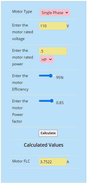 PicoMite, Armmite F4, SensorKits, MMBasic Hardware, Games, etc. on FOTS |
||||
| Mixtel90 Guru Joined: 05/10/2019 Location: United KingdomPosts: 8911 |
Ah... Firstly, your device is reporting kWh then, not kW. :) kW is the power drawn by the motor. You may find a motor rated in hp or kW. kWh is the total power used by the motor over a period of time. 1kWh is 1kW for 1 hour or 2kW for 30 mins or 0.5kW for 2 hours. The two are different things. That calculator looks wrong. I think it's actually using a 240v setting no matter what you specify. :) https://www.rm-electrical.com/technical-resource/motor-current-charts/ https://www.hydrospares.co.uk/help-advice-centre/help-articles/pumps/motor-current-lookup-chart.htm Edited 2021-08-20 01:02 by Mixtel90 Mick Zilog Inside! nascom.info for Nascom & Gemini Preliminary MMBasic docs & my PCB designs |
||||
| lizby Guru Joined: 17/05/2016 Location: United StatesPosts: 3784 |
I think that's what I was saying some posts ago (if we're talking about the same thing). The GUI site "Power" line in watts is the rate which, if maintained over the course of an hour, would use that many watt-hours. In fact, divided by the approximately 1-minute run time (1033/60=17.2) gives about the watt-hours used which is reported by the telemetry, 14-watt-hours. Here's another FLC calculator which gives (nearly) the same results as the other one, including the formula it used to make the calculation. Is there something wrong with that formula, or why does the result differ so significantly from the charts you link to? 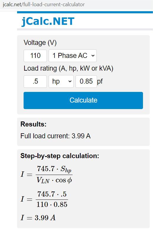 ~ Edited 2021-08-20 01:39 by lizby PicoMite, Armmite F4, SensorKits, MMBasic Hardware, Games, etc. on FOTS |
||||
| Mixtel90 Guru Joined: 05/10/2019 Location: United KingdomPosts: 8911 |
I've no idea. :) There are plenty of engineering sites that disagree with such a low current. https://www.engineeringtoolbox.com/elctrical-motor-full-load-current-d_1499.html Remember that the designed rating and FLC of a motor is what's written on the nameplate though. Everything else (including calculation) is a generalization. Motors vary a lot in efficiency. Efficiency varies with load, as does load current. If your pump is very lightly loaded then it's quite possible that the current drawn is very low. The FLC is the *maximum* current that the motor should be allowed to draw. Edited 2021-08-20 02:27 by Mixtel90 Mick Zilog Inside! nascom.info for Nascom & Gemini Preliminary MMBasic docs & my PCB designs |
||||
| lizby Guru Joined: 17/05/2016 Location: United StatesPosts: 3784 |
Frustrating that the calculators and charts differ from each other by about a factor of 2. Nonetheless, the setup appears to be working, and since what I really want is the on and off times (which I could also have gotten with a current transformer), and the power usage is just a plus, I'm happy so far. The next question is whether the AIMS auto transfer switch inverter will be able to deliver the startup surge from a battery. A second POWR2 will enable me to test this by turning off the mains supply. It will take me a while to get to that, since I also need to set up to monitor the battery voltage to make sure I don't run it down too far. It will be interesting to see how many 1-minute cycles I can get from the battery I have--an idea of how long we can continue to have water if the power goes out. PicoMite, Armmite F4, SensorKits, MMBasic Hardware, Games, etc. on FOTS |
||||
| Mixtel90 Guru Joined: 05/10/2019 Location: United KingdomPosts: 8911 |
It might be worth getting a clip-on ammeter with MAX reading then you can *know* the motor starting and running current before specifying an inverter. Mick Zilog Inside! nascom.info for Nascom & Gemini Preliminary MMBasic docs & my PCB designs |
||||
| lizby Guru Joined: 17/05/2016 Location: United StatesPosts: 3784 |
Good idea, but I already have the AIMS unit--it either will or won't work. PicoMite, Armmite F4, SensorKits, MMBasic Hardware, Games, etc. on FOTS |
||||
| Mixtel90 Guru Joined: 05/10/2019 Location: United KingdomPosts: 8911 |
That's solved that bit then. :) Mick Zilog Inside! nascom.info for Nascom & Gemini Preliminary MMBasic docs & my PCB designs |
||||
| Page 1 of 2 |
|||||
| The Back Shed's forum code is written, and hosted, in Australia. | © JAQ Software 2026 |
