Notice. New forum software under development. It's going to miss a few functions and look a bit ugly for a while, but I'm working on it full time now as the old forum was too unstable. Couple days, all good. If you notice any issues, please contact me.
galderdi Regular Member Joined: 12/08/2016 Location: AustraliaPosts: 99
Posted: 12:48am 05 Oct 2021
Copy link to clipboard
Print this post
Thanks for the encouragement. This type of ability is certainly hard to find. Too many people would rather take the easy option. I can kind of understand it from a paint shop's point of view. They need to make money and the most cost effective way is often to replace a panel rather than repair it.
My work is far from perfect. Certainly not even good enough to leave as raw aluminium. But as a beginner I am fairly happy. I am learning quickly.
galderdi Regular Member Joined: 12/08/2016 Location: AustraliaPosts: 99
Posted: 12:52am 05 Oct 2021
Copy link to clipboard
Print this post
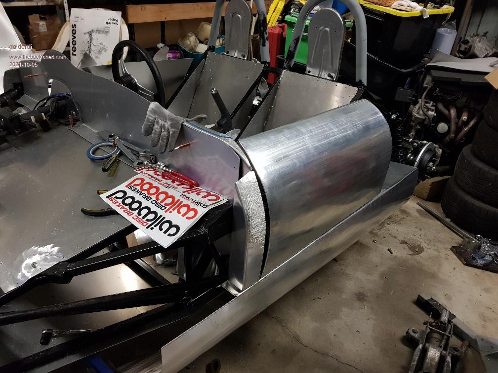
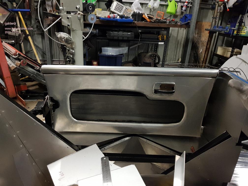
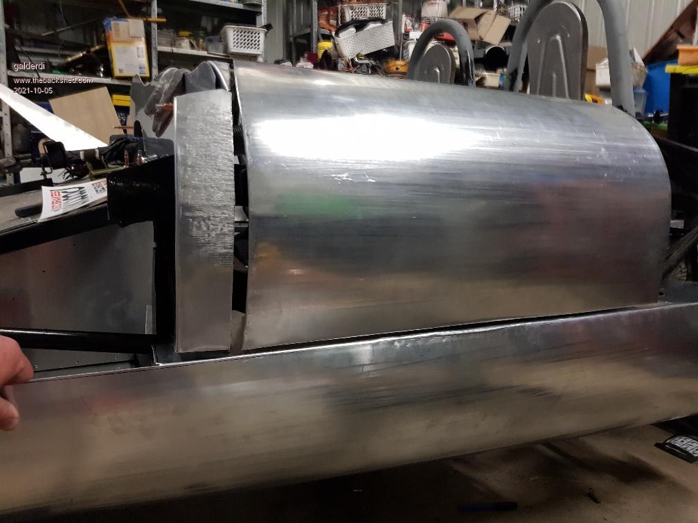
Here is my latest photos. The passenger door is almost complete. I just need to add a small weld at each end of the tube on top. The driver door is now progressing also. The inner panel is formed and attached to the door frame. I need to form the right sill so I can assess and adjust the lower door gap before creating the skin.
I have also started a practice attempt at the dash.
galderdi Regular Member Joined: 12/08/2016 Location: AustraliaPosts: 99
Posted: 10:18pm 24 Oct 2021
Copy link to clipboard
Print this post
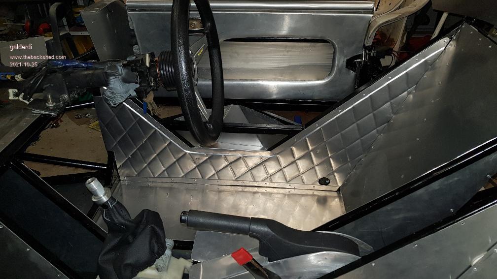
I tried my hand at quilting on the weekend
Davo99 Guru Joined: 03/06/2019 Location: AustraliaPosts: 1577
Posted: 01:49am 25 Oct 2021
Copy link to clipboard
Print this post
Obviously another clear success!
galderdi Regular Member Joined: 12/08/2016 Location: AustraliaPosts: 99
Posted: 10:12pm 31 Oct 2021
Copy link to clipboard
Print this post
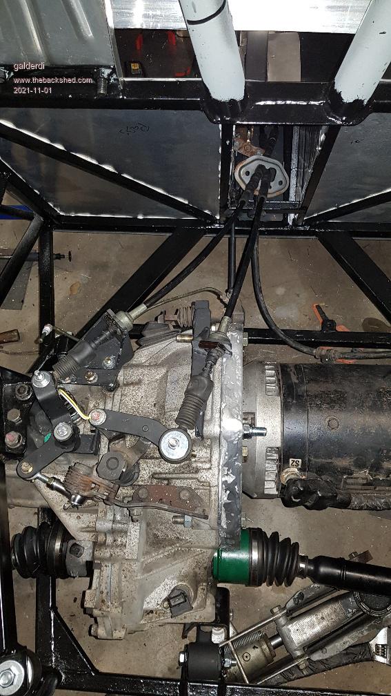
Another productive weekend. I modified the hardware for the shift linkages to allow for the 30mm required. One of the cables was long enough because the small silver linkage had enough adjustment to compensate. But the bracket for the sheath needed to be moved 30mm toward the front. The other sheath bracket also had to be moved 30mm closer to the front and I made a new pivot bracket with less angle to move the cable connection 30mm further forward.
I also made some progress on the panels. I permanently attached the structural panel above the footwell. Then I adjusted the dash and door jam panels to suit their new position allowing for more padding to satisfy the registration rules. I also started playing with moulding some polycarbonate to act as clear screen to protect my gauges as the original screen was too deep and had too much angle to suit my purpose.
Godoh Guru Joined: 26/09/2020 Location: AustraliaPosts: 378
Posted: 01:09am 01 Nov 2021
Copy link to clipboard
Print this post
Looks great, I did not realise that you are making an all wheel drive vehicle. That will make it a great little car to drive. Is that a subaru gearbox you are using? Pete
galderdi Regular Member Joined: 12/08/2016 Location: AustraliaPosts: 99
Posted: 01:56am 01 Nov 2021
Copy link to clipboard
Print this post
Sorry Pete, it's not AWD.
I was originally planning AWD but my engineer steered me away from that plan. He was going to insist on synchronisation methods and extra testing. It would have been a nightmare and would have become a totally different car. In other words twice as heavy. At least this way it will be a very light and nimble little car.
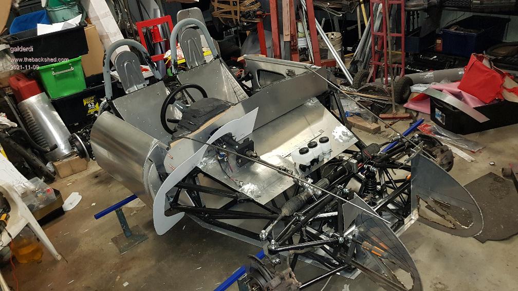
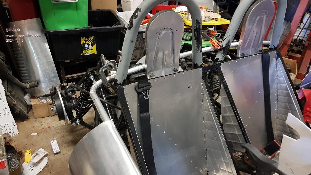
The photo might have confused matters as it is a front wheel drive motor mounted in front of the rear wheels. The rear wheels are at the end of the drive shafts in the photo. The gearbox is from a Hyundai Getz.
galderdi Regular Member Joined: 12/08/2016 Location: AustraliaPosts: 99
Posted: 10:15pm 01 Nov 2021
Copy link to clipboard
Print this post
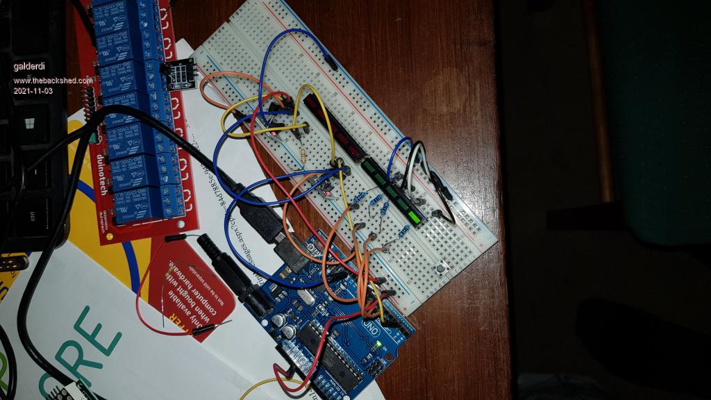
Last night I started a trial run using an Arduino to run a series of temp sensors. The sensors are a safety feature. If the batteries get to a certain temp I need to ease off on the accelerator. The sensors I am using can be run in series and provide a digital signal. I purchased 2 sensors for the trial run but my hope is to use 45 to have a sensor for each set of battery cells. I need to prove that 45 will work in series and drive some form of visual output. I successfully got 1 sensor working but couldn't get the second one working. I thought I either had the wiring or programming wrong. But then I swapped the sensors over and still couldn't get the second one working. So I am fairly sure it is a faulty sensor. I plan to purchase a couple more sensors and some other items to continue the trial tonight. I need to decide on the best way to display the result.
I think displaying the individual temps for 45 sensors would be way too difficult and would also be an eye sore in the car. I was thinking of 2 x 7 segment displays to provide the highest temp rounded to the nearest digit. But even that would be an eye sore. My current thinking is to have a single bar of 10 LEDs with 7 green and 3 red. Each LED would represent 10 degrees. Before driving it should sit at 2-3 LEDs. Normal driving might see 3-4 LEDs. If it gets to 5-6 it's time to back off. Any higher than that would be cause for concern and time to stpp driving entirely. The LED bar is only 61mm long and 5mm high so I think it will be the neatest solution.
I also need to modify the code so that it drives another LED to warn if any of the sensors go off line.
As a side note the motor controller also has a temp sensor for the motor and can drive the standard temp gauge in the cluster.
galderdi Regular Member Joined: 12/08/2016 Location: AustraliaPosts: 99
Posted: 10:47pm 02 Nov 2021
Copy link to clipboard
Print this post
I made some good progress on the temp sensors last night. With a replacement sensor I managed to get the test working. I went to a different store and opted for 5 green LEDS and 5 red LEDs but the principle is still the same. I worked out how to get the logic to recognise the highest temp from any sensor. Then I worked out how to drive the LEDS to reflect the highest temp. For the purpose of the test I had it calibrated to trigger 0 LEDs less than 29.5 degrees, 1 LED between 29.5 and 30 and 2 LEDs above 30. This allowed me easier control to raise or lower the temp for the tests.
So that proves the theory. I have ordered all the sensors. Once they arrive I will need to perform another test to prove the system can handle 45 in series. Then I just need to alter the code to calibrate for 10 degree increments and replace this temporary circuit with the permanent one........I love arduino
Godoh Guru Joined: 26/09/2020 Location: AustraliaPosts: 378
Posted: 09:15pm 03 Nov 2021
Copy link to clipboard
Print this post
Fantastic work, that is one amazing project. Obviously you are very motivated. Arduino's are fantastic things, I never learnt enough about coding them but managed to get one to work a solar hot water pump system once. It just kept working for years. Have fun and thanks for the updates on your project Pete
galderdi Regular Member Joined: 12/08/2016 Location: AustraliaPosts: 99
Posted: 10:33pm 03 Nov 2021
Copy link to clipboard
Print this post
Thanks Pete. I too am a novice on Arduino. I only manage by copying and modifying code from other people. I guess that is what makes these platforms so powerful for the average Joe.
Last week I finalised the dash position (I hope). So that clears the way to start building shape in front of the doors and dash. So things are getting real now. For a long time I have been looking forward to starting to produce some real body shape. One of the challenges I have been thinking through is the need for some inner support/border panels around the inside of the bonnet. I roughly know where I want them but trying to work out the upper contour. The the upper contour of these panels needs to precisely match the contour of the bonnet and surrounding panels. I now have the dash height and position. My plan is to build the nose structure. Then I will make a guide bar following the contour based on my buck. Then I can use that guide to reproduce the same contour on these inner panels. That's the theory anyway. What could possibly go wrong :-D
galderdi Regular Member Joined: 12/08/2016 Location: AustraliaPosts: 99
Posted: 10:51pm 03 Nov 2021
Copy link to clipboard
Print this post
The other challenge I am facing in the bonnet area is allowance for the impact of bead rolling. I plan to use the bead roller for both the inner panels and the bonnet itself. For the inner panels I need to create some steps for the bonnet recess. For the bonnet it will have a frame around the outside to provide some strength. The frame will have a bead rolled in around the perimeter to stiffen the structure. The challenge comes from the bead roller altering the contour of the panel. There won't be much ability to bend it back after the process. So I need to add additional shape before I bead roll. Then the bead roll will bring it back to where it needs to be. I will need to do a test run to understand how much allowance is required.
My head is spinning.
galderdi Regular Member Joined: 12/08/2016 Location: AustraliaPosts: 99
Posted: 04:19am 08 Nov 2021
Copy link to clipboard
Print this post
I made a little more progress over the weekend but nothing was really photo worthy. I did a little more work on the front door jams with some trimming and grinding. But more is required. It was enough to enable me to mount the driver door in place and checked the alignment and gap. I am fairly happy with those results. I need to do the same check on the passenger side.
I redid a fair amount of work on my practice dash to allow for the revised position. The passenger side is coming together but the driver side needs a heap of thought and work.
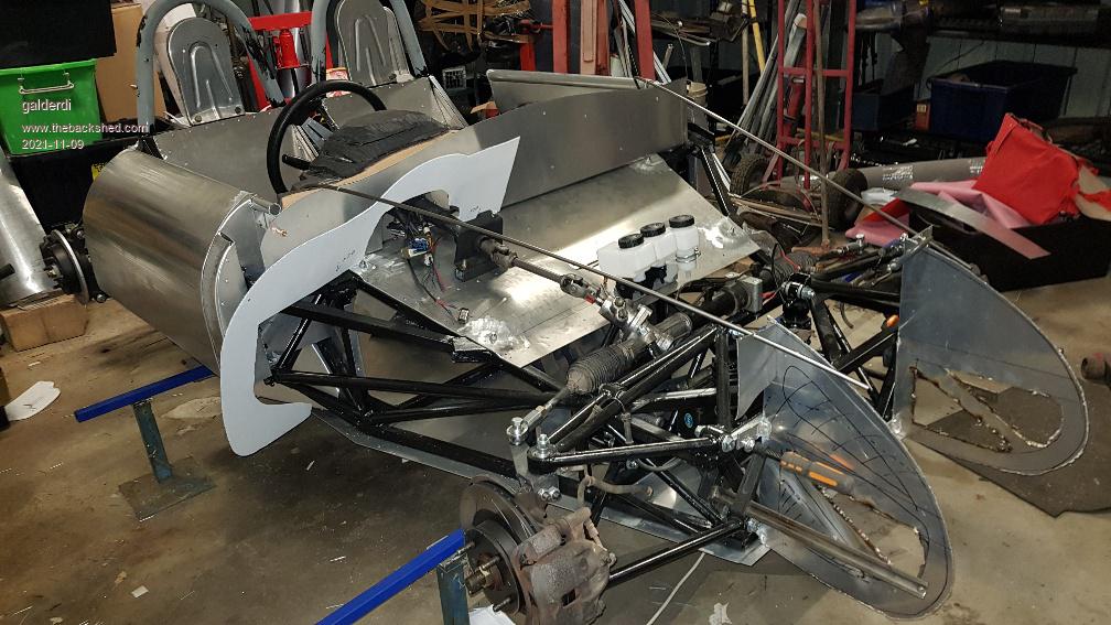
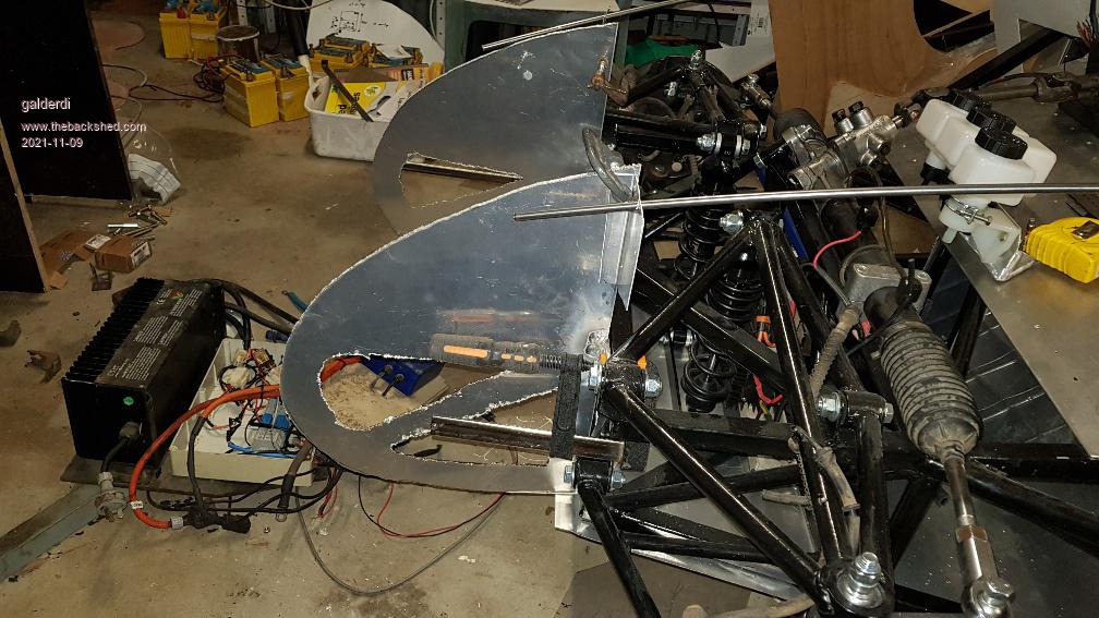
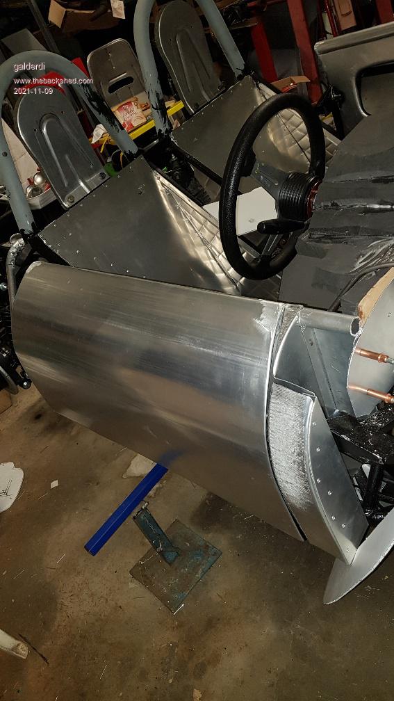
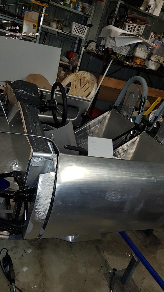
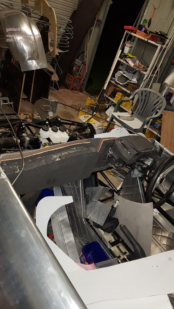
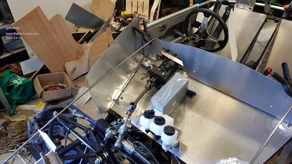
I started work on the nose support structure. This is basically some aluminium framework extending in front of the chassis to support the nose panels. It will also provide the mount point for the bonnet hinge. This structure is important at this point because I plan to start work on the panels around bonnet area and I need points of reference to ensure the heights are correct. I have created a couple of steel bars which match the contour of the bonnet. I will use these bars to span the gap between the nose structure and the top of the dash. This will give me the height and the outline of the bonnet. Then I can build the panels that will extend up from the chassis to these bars. The top edge of these panels will support the front guards and will incorporate a recess into which the bonnet will seat. These panels will also become the lining around the usable space under the bonnet. I am still finalising where all the components will go. But I am hoping I can keep them confined to the driver side leaving the passenger side free for some limited luggage.
galderdi Regular Member Joined: 12/08/2016 Location: AustraliaPosts: 99
Posted: 10:15pm 08 Nov 2021
Copy link to clipboard
Print this post
Here are some photos to show the latest progress. Don't mind the rough edges. None of this is finished. But it lines me up for some key panels.
Davo99 Guru Joined: 03/06/2019 Location: AustraliaPosts: 1577
Posted: 10:56pm 08 Nov 2021
Copy link to clipboard
Print this post
The amount of work put into things like this is impossible to appreciate. I helped a mate many years ago Restore a '38 Buick. Spent at least a Night and a weekend day for well over a year on that but still having done it, I can only imagine what you are putting into this. We didn't have to fabricate much at all, it was all there and just needed brining back to scratch. One of the hardest things of all was working out how to re do the pearled steering wheel but we had the wheel itself to start with. What you are doing is another level.
You'll be putting hours into details of things that no one will ever look at, appreciate or notice but will drive you nuts if it's not done just right. No matter how impressive what you are doing is, no one will ever really know just what went into it. We only see the finished result, never see what went in to getting it or the redos and planning to get it that way.
I can only admire rather than fully appreciate your work because I don't have the skills or therefore knowledge to do it myself and therefore know what does go into it. The bit I do know and see you are doing is extremely impressive.
I watch some YT channels with EV's and contemplate the potential in the future when a Large motor can be hooked to each wheel and do away with gearboxes and run mega power to each wheel. I know some of the exotics do that now but it's hugely expensive which is the biggest drawback of Electric atm.
I'd like to do an electric conversion for a yard run around for fetching the firewood and other odd jobs on a Subaru wagon. When I look at the cost and complexity as against just Dropping in a 6 or 9 HP stationary motor with a clutch and some sprockets where the original engine went, I just can't come near Justifying it unfortunately.
Keep up the great work!
galderdi Regular Member Joined: 12/08/2016 Location: AustraliaPosts: 99
Posted: 12:19am 09 Nov 2021
Copy link to clipboard
Print this post
Thanks Davo. My skills have come a long way but I still have a long way to go.
The idea of motors "in" each wheel is generally not a good one. Motors with any decent power are always heavy and add unsprung weight in the wheels which is not great for handling. There aren't too many production cars made this way. However individual inboard motors driving each wheel is a totally different scenario.
I'd be interested to know what EV options you've considered. Not all options are created equal. But I accept an EV conversion is difficult to do cheaply. Hopefully as more EVs become available on the second hand/write off market more budget options will become available.
The cheapest option I can think of is a Truck Alternator conversion. Just find the biggest truck alternator possible, tweak it to become a motor, add a controller, add some batteries and away you go. The down side is they are usually used for a gokart sized vehicle so I'm not certain it would work for a Subaru.
Another budget option is to find a forklift motor. With some patience you might get lucky and find a really cheap forklift motor. But you still need the battery and controller.
Another option that is becoming more common is repurposing a Nissan Leaf motor. This can be done with the factory controller or there are after market controllers which significantly increase the power.
Davo99 Guru Joined: 03/06/2019 Location: AustraliaPosts: 1577
Posted: 05:58am 09 Nov 2021
Copy link to clipboard
Print this post
galderdi Regular Member Joined: 12/08/2016 Location: AustraliaPosts: 99
Posted: 12:20am 16 Nov 2021
Copy link to clipboard
Print this post
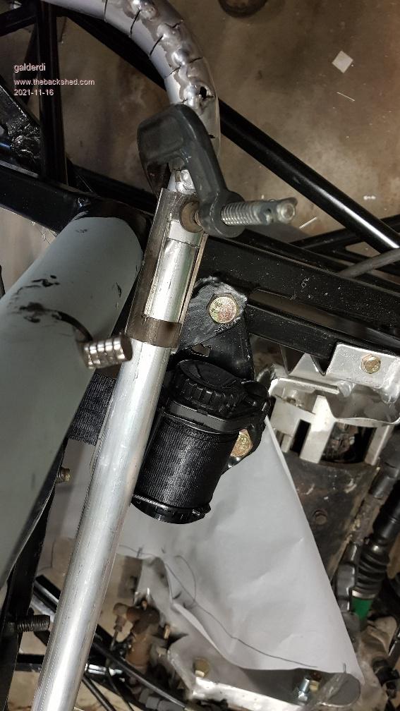
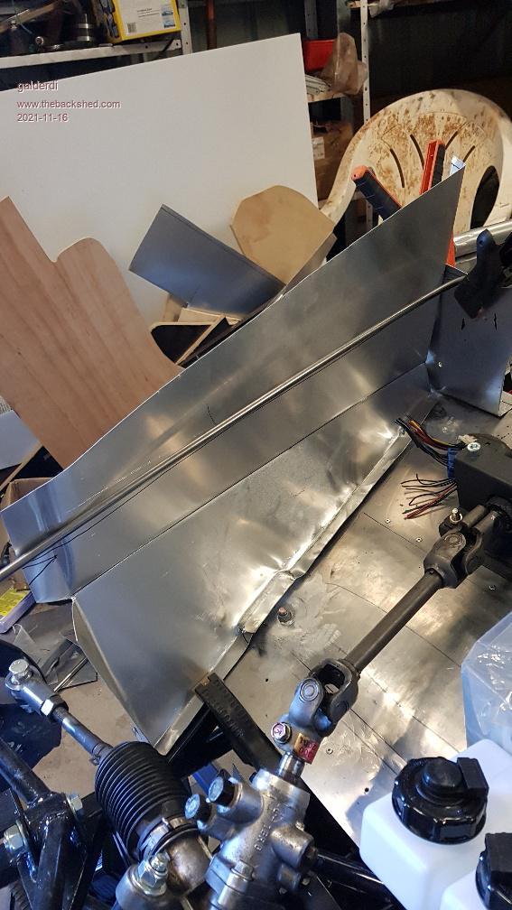
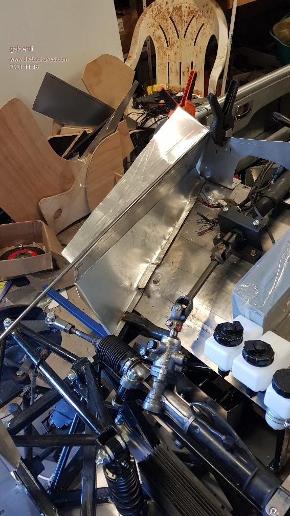
I solved a couple of key challenges over the weekend. The first one was how to secure the tube bends accurately so I can weld them and end up with them in the correct position and angle. I came up with these little brackets which are made from a steel tube one size larger than the aluminium tube. I split it in two parts and cut a window in each side so I can weld through it while it is clamped in place. The second challenge was the inner panels under the bonnet. I made a guide so I know where the edge of the bonnet needs to be. But the edge of the bonnet does not line up with the edge of the chassis. I thought about twisting the panel or putting some shape into it to get it to twist. But I think the accuracy would have suffered. The edge needs to be straight on the vertical plane but follow the bonnet curve on the horizontal plane. What I came up with is a bend part way down the panel. I am happy with the result. It gives me the ability to adjust the top edge of the panel to line up fairly accurately with the intended bonnet line.
zeitfest Guru Joined: 31/07/2019 Location: AustraliaPosts: 377
Posted: 09:25am 04 Dec 2021
Copy link to clipboard
Print this post
Been watching this for a while... inspiring plus.
Is the chassis design available ? I guess certification is pretty expensive
galderdi Regular Member Joined: 12/08/2016 Location: AustraliaPosts: 99
Posted: 11:55pm 05 Dec 2021
Copy link to clipboard
Print this post
That depends what you mean by available. If you mean can you download it and build it yourself the answer would be no. It is licensed and can only be produced under agreement. Sunshine Coast Sports cars has that agreement here in Australia. They only planned to make 10 chassis and this is the last of the 10. But I wouldn't say it is impossible to convince them to build another.
Certification can be very expensive if you are starting with a chassis your engineer has not previously tested. There is a whole raft of tests and facilities required. It would literally cost in excess of $7000 possibly more than $10000. Plus there is every chance it could fail the tests triggering redesign and retesting.
Working with a known quantity eliminates all that.
Having said that, I am still faced with a long list of requirements and decisions in order to have it registered. For example the dash padding which forced me to deviate from the original Porsche design and move the metal part of the dash forward and include a large padded area. There are many other examples but I won't bore you with them all. They are all in the Main Roads/Australian standards.