
|
|
Forum Index : Microcontroller and PC projects : Waveshare Pico Toys
| Author | Message | ||||
| phil99 Guru Joined: 11/02/2018 Location: AustraliaPosts: 1773 |
The picture looks like a dud panel, missing the light guide / diffuser that spreads the light evenly over the whole surface. Even with a second row of LEDs on the other side the middle would be a bit dark. Or they have used the wrong size LEDs and the light is entering the light guide at the wrong angle. Edited 2021-10-18 09:49 by phil99 |
||||
| geoffw Newbie Joined: 09/01/2018 Location: AustraliaPosts: 2 |
I have this display now working with Peter's latest beta. Waveshare RTC module is mounted with the Pico. Screens below are taken with brightness at 75 and lighting is good across the screen. The photo showing the top of my screen is quite different, I would suspect a manufacturing fault. 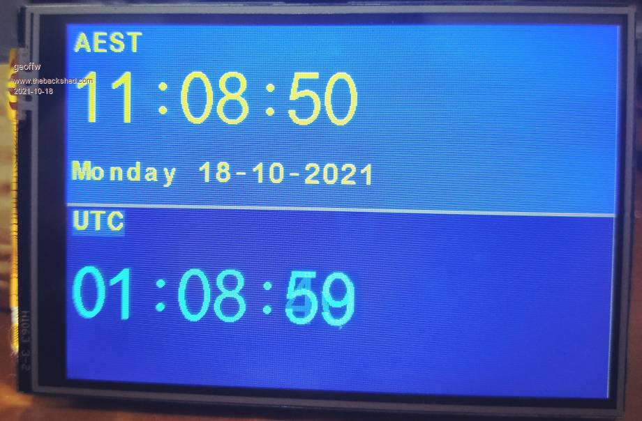 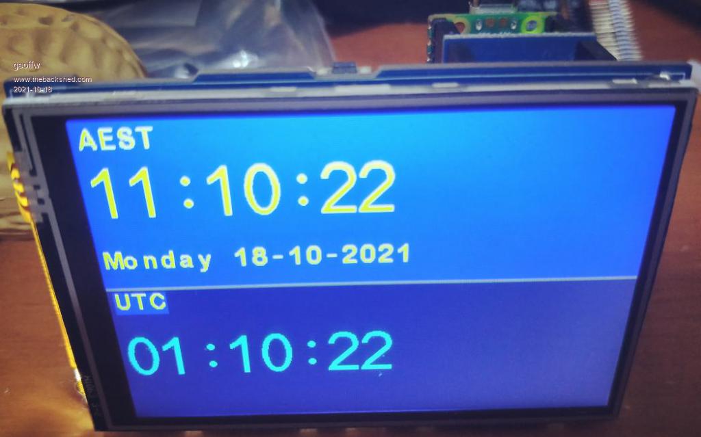 Geoff |
||||
| Poppy Guru Joined: 25/07/2019 Location: GermanyPosts: 486 |
Still trying to get the whole issue correctly. Is it correct that 2,8" Waveshare displays generally cause no problems and the 3,5" items of the same product line do? And now proven by Geoff they do work on the latest update by Peter without any problems? Or do they just work basically by now?  Andre ... such a GURU? Andre ... such a GURU? | ||||
| matherp Guru Joined: 11/12/2012 Location: United KingdomPosts: 8567 |
The Waveshare 2.8" (ST7789) works perfectly including transparent text and blit. From b29 onwards the 3.5" (IILI9488 wired parallel with shift registers to create SPI I/F) works properly but cannot support transparent text and blit as the H/W I/F is out only (therefore I can't read the framestore). Note the ILI9341 has always supported transparent text and blit with no issue For the same reason as the 3.5" the various ili9841 cannot. The normal SPI wired ILI9488 can support transparent text and blit but is then not compatible with SDcard on the same pins and touch (bug in the ILI9488 controller) The smaller Waveshare ST7789 displays cannot support transparent text and blit as Waveshare don't bring out the MISO pin. Who said it was easy  Unless you need the bigger screen real estate the 2.8" ILI9341 or ST7789 are the preferred displays Edited 2021-10-18 21:14 by matherp |
||||
| Poppy Guru Joined: 25/07/2019 Location: GermanyPosts: 486 |
Thanks Peter, now I perfectly got it and know what and how to do it!  Andre ... such a GURU? Andre ... such a GURU? | ||||
| cdeagle Senior Member Joined: 22/06/2014 Location: United StatesPosts: 261 |
This post describes a simple handmade case for the Waveshare 2.8 inch pico. The case is created using a Zulkit 90 x 70 x 28 mm plastic case available on Amazon. Five cases cost $10 USA. Here's a picture of the contents of each case. The rectangular pieces are side panels for the case. 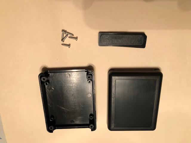 One side of the case includes a "depressed" area that is the perfect size for the 2.8 inch display. This area is removed using an Xacto knife and hobby backsaw. I first score the edges of this area several times with the Xacto knife and finish using the backsaw. The plastic in this area is thinner than the rest of the case. 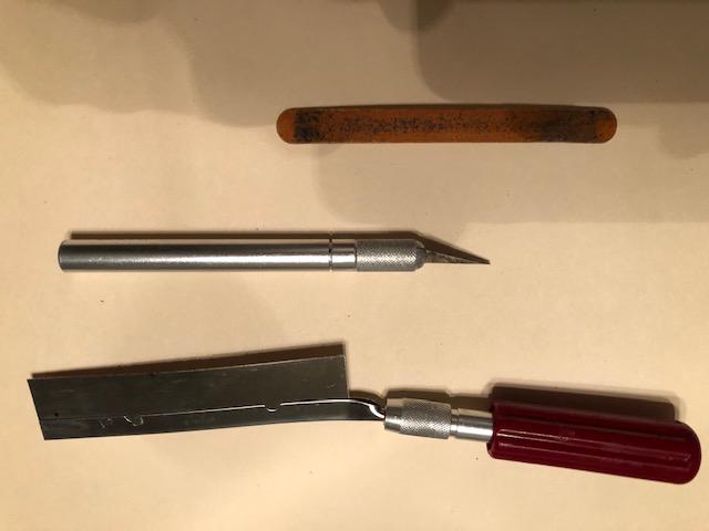 The edges are cleaned with an emery board. Here's a picture of the top and bottom of the case. 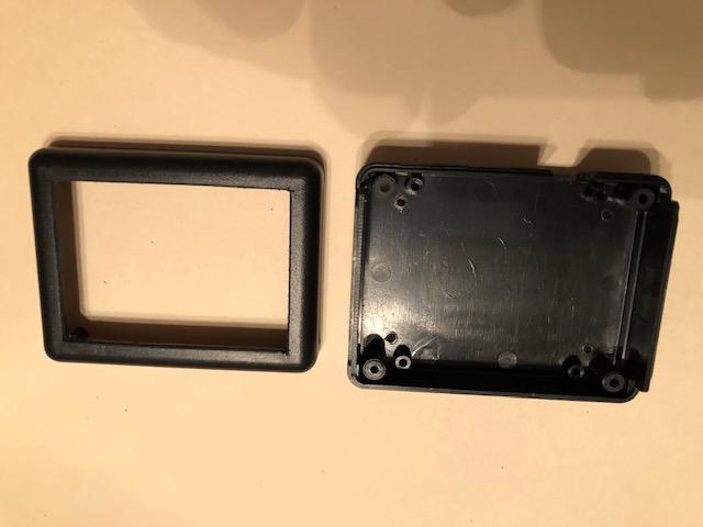 I use a paper template to locate holes in the case bottom for mounting the standoffs included with the pico as shown in this next photo. The holes can be created with the Xacto or a small drill. I use four small machine screws to attach the standoffs/pico. 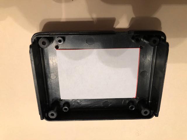 Finally, an opening for the usb cable is cut in the side of the case bottom using the backsaw. Two slots can be cut slightly wider than the usb cable. The plastic can be snapped off using needle nose pliers and cleaned up with the emery board. 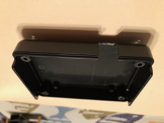 Here's a picture of the completed case. I place four small bumper feet on the bottom so the case does not slide. 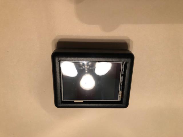 |
||||
| cdeagle Senior Member Joined: 22/06/2014 Location: United StatesPosts: 261 |
Here's a picture of a "PicoGPS" using the previously described case. This project included a Waveshare GPS with an active antenna and Voltaic rechargeable battery. The display shows everything available via the MMBASIC GPS function. 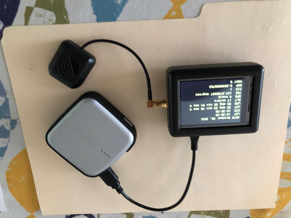 |
||||
| Tinine Guru Joined: 30/03/2016 Location: United KingdomPosts: 1646 |
@cdeagle: Very nice I like this particular 2.8" display and am contemplating a printed enclosure. I would like to come up with a seal between the bezel and the display; maybe print a channel around the perimeter and glue o-ring stock in the channel. I don't have the display yet but do you see a problem with the idea? |
||||
| Mixtel90 Guru Joined: 05/10/2019 Location: United KingdomPosts: 5705 |
As the display area is smaller than the physical display it should be possible to use an accurately cut hole, possibly beveled. with the display behind it. That's what I tried to do when I tried putting an ILI9341 in a box. It was tricky trying to line up the fixing screws with the hole though. It might not be too good putting the display hard up against the front anyway as it's a resistive touch screen so any pressure round the edge might possibly cause a problem. Eventually I settled on using 6mm spacers with that screen to leave a gap of about 1mm. Unfortunately my rectangular hole cutting skills weren't too brilliant, but as a proof of concept it was reasonable. :) Mick Zilog Inside! nascom.info for Nascom & Gemini Preliminary MMBasic docs & my PCB designs |
||||
palcal Guru Joined: 12/10/2011 Location: AustraliaPosts: 1796 |
I have the 2.8" display working, I want to control the backlight. The Pin marked LCD_BL on the display goes to Pin GP13 which is CS. Which pin do I use for PWM control of the Backlight. Edited 2021-11-01 15:36 by palcal "It is better to be ignorant and ask a stupid question than to be plain Stupid and not ask at all" |
||||
| matherp Guru Joined: 11/12/2012 Location: United KingdomPosts: 8567 |
option lcdpanel ST7789_320,gp8,gp15,gp9,gp13 BACKLIGHT n 'n=0 to 100 |
||||
| palcal Guru Joined: 12/10/2011 Location: AustraliaPosts: 1796 |
Thanks I could not find in the manual what the fourth pin was for. Got a bit mixed up there. "It is better to be ignorant and ask a stupid question than to be plain Stupid and not ask at all" |
||||
| matherp Guru Joined: 11/12/2012 Location: United KingdomPosts: 8567 |
Looks like the manual is a bit behind on this. Will let Geoff know |
||||
| Tinine Guru Joined: 30/03/2016 Location: United KingdomPosts: 1646 |
I'm brand new to this display stuff and have the 2.8" and settings as above. But orientation is missing here, right? So, I need a jump-start, here....how do I get a simple "hello world" on this thing? I just pulled my rig apart to reorganise my workspace so it's going to be a couple of hours before I get to play |
||||
| Mixtel90 Guru Joined: 05/10/2019 Location: United KingdomPosts: 5705 |
Yep - looks like orientation is missing. Perhaps Peter was looking from the back of the display and couldn't see it at the time? ;) Make sure your display has a CS pin or you might be unhappy and say naughty things that might slow your heavenly progress in the future... Try: (set your OPTION SYSTEM SPI) OPTION LCDPANEL ST7789_320 L, GP8, GP15, GP9, GP13 (OR, DC, RESET, CS, LCD) BACKLIGHT 60 TEXT 10, 10, "Hello World!" Mick Zilog Inside! nascom.info for Nascom & Gemini Preliminary MMBasic docs & my PCB designs |
||||
| Poppy Guru Joined: 25/07/2019 Location: GermanyPosts: 486 |
I just ordered this one. (Not having received yet) GP13 is labeled "LCD_BL", meaning "LCD Backlight"?!?! Would You guess this is meant to work? Edited 2021-11-07 20:39 by Poppy Andre ... such a GURU? | ||||
| lizby Guru Joined: 17/05/2016 Location: United StatesPosts: 3008 |
Somewhat pricy but a nice 3.5" 480x320 LCD. If picomite MMBasic could be made to support BLIT READ with this LCD, that would be a nice addition to the kit. PicoMite, Armmite F4, SensorKits, MMBasic Hardware, Games, etc. on fruitoftheshed |
||||
| matherp Guru Joined: 11/12/2012 Location: United KingdomPosts: 8567 |
Completely impossible - check the schematic for this board and you will see why |
||||
| Poppy Guru Joined: 25/07/2019 Location: GermanyPosts: 486 |
Sorry Mick, was just playing with words too much  Real question: Do You think this Version shown on the linked Pic will do it? Andre ... such a GURU? | ||||
| Mixtel90 Guru Joined: 05/10/2019 Location: United KingdomPosts: 5705 |
https://www.waveshare.com/w/upload/8/85/Pico-ResTouch-LCD-3.5_Sch.pdf It should work. LED_BL goes to the EN pin of CAT1, which seems to be a controllable voltage regulator feeding the backlight LEDs. Their cathodes are then groundedd by R17, R18 & R19. It's a weird display, using a parallel LCD panel and a pseudo SPI system using shift registers to turn it into a serial one. There's also a SRAM on board with a SRAM_CS signal on GP2 but why? MISO doesn't read anything back from the display (it has no read signal) so no transparent text or blit on this display. Edited 2021-11-08 17:59 by Mixtel90 Mick Zilog Inside! nascom.info for Nascom & Gemini Preliminary MMBasic docs & my PCB designs |
||||
