
|
|
Forum Index : Electronics : Another MPPT controller
| Page 1 of 2 |
|||||
| Author | Message | ||||
| Murphy's friend Guru Joined: 04/10/2019 Location: AustraliaPosts: 581 |
This project is based on Poida's & Wiseguys inputs to this forum. I did my own PCB to fit an existing (ex Victron energy)heatsink. With help from a local programmer (Gaspo) I got the two nano's programmed. Nothing blew up when I powered it up but I ran into calibration issues, most likely due being last in class with regard to inputting data. Anyway, I managed to set Vin and Vout no problem but do not quite get that "set the zeros for the two current sensors" part. On the cal menu page it shows under 'G' and 'H' 511 ADC counts. Is that what needs to be set to zero or some small offset? I'm using Allegro xxxx-050U-xxx sensors. They have a small output voltage when passing no current. How do I convert this current into ADC counts or need I do that? Further, while it says MPPT on the first item, 4th line, the rest of this line is meaningless, how to I select what can be selected? Also, the NTC temperature display makes no sense, do they need calibration? Their room temp resistance is around 8KOhm. I'm charging a 48V nom. LITHIUM battery bank, I changed the default max battery Volts to 58V, absorb V to 56V and float V to 55.5V I do NOT want equalising with these batteries so I left the nano inputs (D2&D3) for this open - nothing connected. My build, no display fitted: 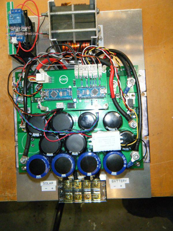 And powered up: 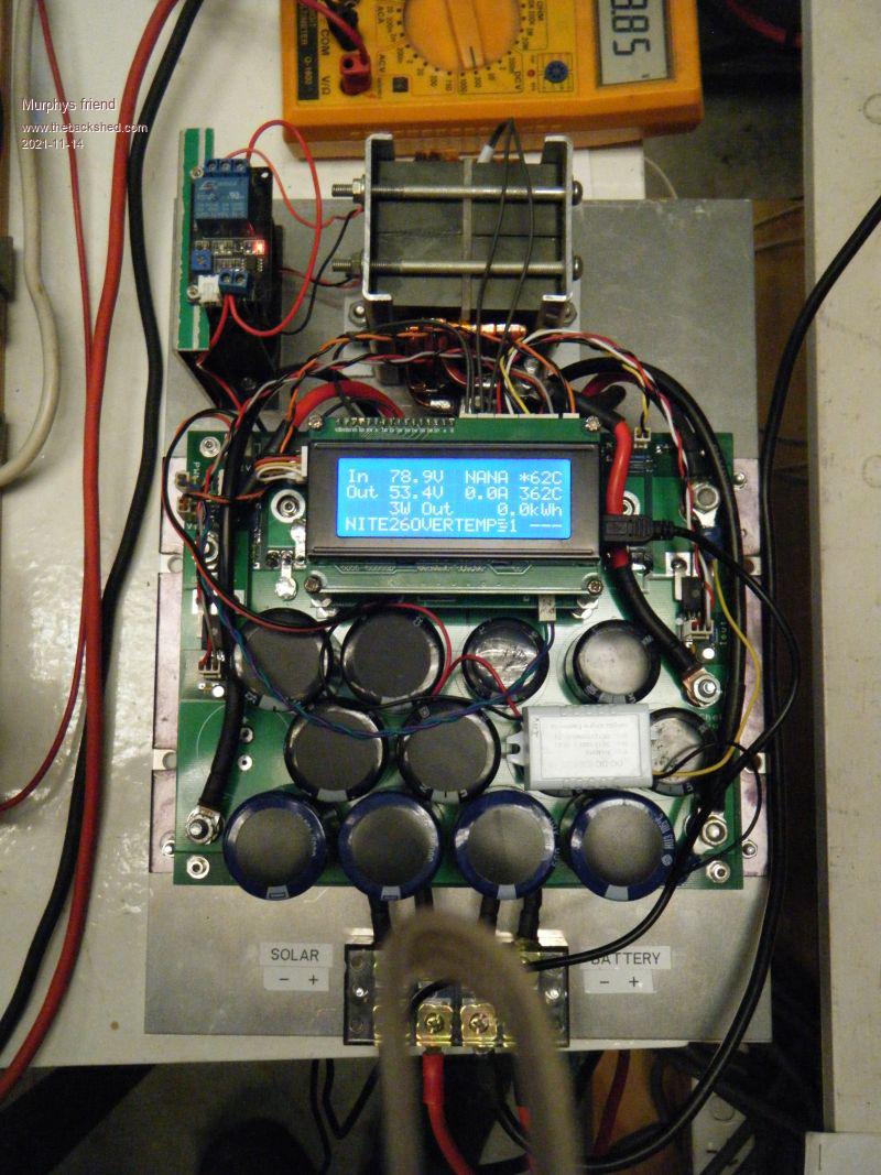 As it is not doing any MPPTing yet your input would be very much appreciated. |
||||
| poida Guru Joined: 02/02/2017 Location: AustraliaPosts: 1388 |
awesome! good to see someone doing something further, to suit what you need with the designs. you wrote: Anyway, I managed to set Vin and Vout no problem but do not quite get that "set the zeros for the two current sensors" part. On the cal menu page it shows under 'G' and 'H' 511 ADC counts. Is that what needs to be set to zero or some small offset? I'm using Allegro xxxx-050U-xxx sensors. They have a small output voltage when passing no current. How do I convert this current into ADC counts or need I do that? Firstly, it's good to see you chose 050U type, this is 0 - 50Amp sensor and it will have a small offset on the output at zero current. So, to set this in the firmware, you choose 'G' with no current passing through the input current sensor. After a little, it will reprint the menu and it will have obtained a good estimation of this offset. The menu will show the offset in ADC counts. ADC counts range from 0 to 1023 which correspond to 0 to 5V. 1023 = 5V (or near enough) And then to set it for the output, choose 'H' with no current going through the sensor. It will store this offset. Might be the same for the input sensor, might be a bit different. No matter. Now, the way I do it, after setting the zero current offsets for both sensors, is to apply a known current across the sensor sense pins. I use a bench power supply, set to 6 Amps and then choose 'E' where the program asks me "dude, what current is this?" I tell it 6.0 and it is happy. Then on to the output sensor, put 6 Amps across it. Note well that direction is important. DO not muck up the current direction. On the input, put +ve current source on the Vin pin. On the output, put current -ve source on the Vout or battery pin. Calibration is easy, just do it. If no bench supply, make a 5 amp current source using a 12V battery, 60W globe and two wires leading to the current sensor. Use the DMM to get the exact current of this circuit. To get it right with 5 or 6 Amps to 2 digit accuracy is enough to get you started. The LCD tells all. First line: Input voltage, Input current and heatsink temp. To see sensible values you need to calibrate the input voltage and current and have a 10K NTC thermistor connected to the system. And tell it which way the thermistor is connected - ground or 5V.. I need to know the firmware you are using. Second line: Output voltage or battery voltage, output current and inductor temperature. Third line: the output power. This is Vout x Iout. If either of these values are rubbish then this power calculation will be rubbish. And the accumulated energy. This is power (in Watts) x hours Fourth line: The operating STATE (one of MPPT, NIGHT, ABSORB, FLOAT,EQUALISE) Then 2 digits counting up from zero to 60 (ie second counter) that is showing when it will check again if Vin is high enough to be useful and change mode from NIGHT to MPPT The next number is the target voltage. This is what the code will want to get the Battery or Vout terminal to. Of course it will change depending on STATE (ABSORB or FLOAT) I have and use a version that uses the inductor sensor input as a battery temperature input and then adjust the target voltage to suit depending on the battery temp. I do not care how hot the inductor gets, they feel no pain. But I do care about overcharging the battery. The next number is PWM width in 8MHz clocks, where 1 = minimum width and 799 is FULL POWAH!! NAN means uncalibrated or unconnected input. Tell me which firmware you are using so I can get on the same page. Edited 2021-11-14 16:46 by poida wronger than a phone book full of wrong phone numbers |
||||
| poida Guru Joined: 02/02/2017 Location: AustraliaPosts: 1388 |
Finally, these things are strong. I have had 3.5kW through them, at 55V output. Nicks has had it higher than that but he's crazy and the laws of physics don't apply in Europe. For reliability, I choose 45 Amps at 55V as a sort of max output power. wronger than a phone book full of wrong phone numbers |
||||
| Murphy's friend Guru Joined: 04/10/2019 Location: AustraliaPosts: 581 |
Thanks Poida, that was quick  . .The software version is mppt V5_BV_tempco. I managed to calibrate the current sensors. The display now reads this: 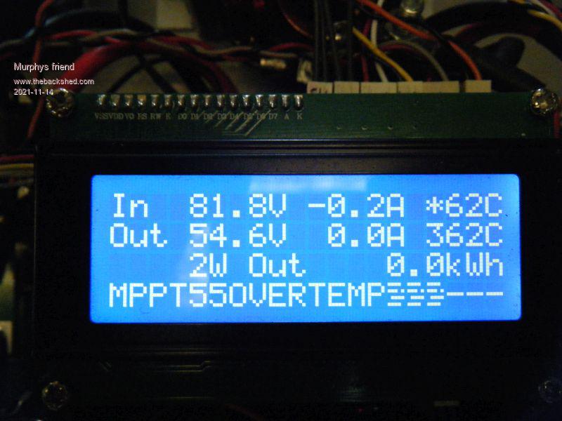 Could that overtemperature reading prevent it from mppting? I do not have a battery temperature monitoring installed, these 200Ah lithium cells do not seem to get warm even with 100+ Amps charging them. All I need is the mppt to stop charging once the absorbing time has finished and the Voltage stays below 58V. This home built MPPT is meant as a reserve unit to my other 2 charging methods (2KW back charging via inverter and a60A Outback MPPT charger) |
||||
| gaspo Regular Member Joined: 25/06/2018 Location: AustraliaPosts: 61 |
Is the first thermistor you are using 10K NTC? It seems to read too high: 62C. If you are not using second thermistor input connect 10K resistor in its place, should then read ~25C. Edited 2021-11-14 19:42 by gaspo |
||||
| Murphy's friend Guru Joined: 04/10/2019 Location: AustraliaPosts: 581 |
Thanks gaspo, good idea. I measured several "10K" thermistors I have here, they measure ~8KOhm at room temp. I'll make some plug in 10K resistors tomorrow and see what that does - easy mod. |
||||
| poida Guru Joined: 02/02/2017 Location: AustraliaPosts: 1388 |
the message "OVERTEMP" means the code sees an over temperature condition and has stopped mppt-ing. Maybe get back into the menu and disable overtemp shutdown by setting heat sink max temp to something large, 1000 I like putting a 10K on the thermistor input pins. This will make them 25C and this will be so for both choices of wiring... The calculated temperatures are only gong to be close to reality when you use 10K NTC thermistors AND you have correctly set the option in the menu "3 - NTC 5V or GND (= 1 if 5V, = 0 if GND) " If your thermistors have one pin connected to ground, then you choose 0 If you have one pin connected to 5V supply (high side of voltage divider) then choose 1 The firmware needs to do different calculations of the voltage divider depending on the position of the NTC thermisors in the circuit. wronger than a phone book full of wrong phone numbers |
||||
| Murphy's friend Guru Joined: 04/10/2019 Location: AustraliaPosts: 581 |
Thanks to your excellent suggestions I now have managed to trace and correct what I did wrong with the temperature sensors. I now get this display (with 10K resistors fitted): 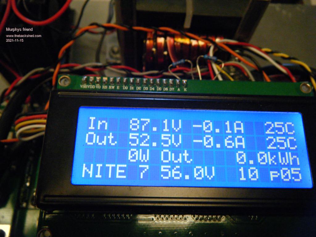 Unfortunately the nano has now decided to remain in the 'NITE' condition, any suggestion how to wake it up? The voltages shown are what I measure at the terminals. No current since its asleep. Thank you for your patience with my MPPT build. |
||||
| poida Guru Joined: 02/02/2017 Location: AustraliaPosts: 1388 |
have you set M - Night power (in Watts) yet? I have it as 5 Watts. If it's not set yet, it might be NAN and so the mppt scan probably will fail, and then no transition from NITE to MPPT/ABSORB wronger than a phone book full of wrong phone numbers |
||||
| Murphy's friend Guru Joined: 04/10/2019 Location: AustraliaPosts: 581 |
Have changed that from 10 to 5 watts now. The display changed from 'MPPT' to 'ABSORB' after I applied a heavy load to my battery bank. But I still cannot see any current on the display nor is any fed to the battery. I changed the FOD3182 just in case - no difference. I have a very small battery operated digital scope that shows a steady stream of narrow pulses at 50us intervals. That changes to a 'wider pulse train' every 60 seconds and then reverts back. Sorry, I do not have the fancy equipment nor the knowledge to use it to troubleshoot. I'm hoping your suggestions keep coming until I got it going  . . |
||||
| poida Guru Joined: 02/02/2017 Location: AustraliaPosts: 1388 |
the steady stream of narrow pulses is normal. It is the 1 clock wide PWM pulse. I am wondering if both current sensors are showing correct values. Should the input current sensor be wired backwards, increasing current will make for negative power during the mppt scan. The mppt scan looks for the largest power for the range of PWM duty cycle widths from 5 clocks to near 100% duty width. It expects power to increase from very small at 5 clocks and to increase steadily to some maximum at some other PWM duty width. The wider pulse train is normal and it is the result of the mppt scan which is done every minute (the second by second count on the LCD will show you when) Maybe you could try running the buck converter firmware on your power board. This code will take the voltage present on A5 pin on the nano as the drive for PWM width. I have used this code very often (in particular, to characterise various inductors) and it always works. It always drives the mppt board hardware well. You will need some sort of load on the "battery+" and ground terminals. I am wondering what exactly you have built and what signals are present. the buck converter code is pretty simple. It prints out on the nano serial console Vin, Vout, Iin, Iout using manually set calibration factors in the code. Easy to adjust. I have a potentiometer set up, with ground and 5V on both ends and the wiper going to A5. The LCD is also active, showing this data. The code will prove the hardware works. The code takes the potentiometer setting as the required output voltage and then adjusts PWM width to get it to be this value. Current values are ignored. Just output voltage is to match the pot setting. maybe try buck_converter_nics_1_b1_nano_pwmserial_bb.ino.zip The calibration values will not be correct for you, nor anyone else. Everyone's builds are different. .. xVin = 0.1744; xVout = 0.0900; xIin = 0.235; xIout = 0.244; tIin = 0.00; // leave this = 0.0 tIout = 0.00; // and this oIin = 511; // the offset is nearly 512 which means the board is oIout = 511; // using bipolar current sensors. Yours will need // smaller offsets, like 50 or something octrip = 0; // leave this = 0 .. wronger than a phone book full of wrong phone numbers |
||||
| poida Guru Joined: 02/02/2017 Location: AustraliaPosts: 1388 |
calibration is manual: so we are working with Vin. Vin shows "60V" but the DMM has it at 40V this means the adjustment FACTOR is 40/60 = 0.6666 and we use this with the xVin variable. It is = 0.1744 right now. We need to change it to 0.1744 x 0.666 which is of course 0.1162 Manual calibration. You need to do this if you are playing with the buck converter firmware. wronger than a phone book full of wrong phone numbers |
||||
| Murphy's friend Guru Joined: 04/10/2019 Location: AustraliaPosts: 581 |
Hmmmm. I followed wiseguys PCB layout for the Allegro sensors. Mine are oriented at 180 degrees to his though. From the specs I see pin 4 is the input for unipolar devices so solar IN goes to pin 4 of the Iin sensor and choke out goes to pin 4 of the Iout sensor. I'll do some measurements tomorrow and enter them on my schematic so I can show them here. |
||||
| Murphy's friend Guru Joined: 04/10/2019 Location: AustraliaPosts: 581 |
Thank for that alternative, I need to add an output for 'A5' on one of my spare boards to play with that suggestion. But first as to your previous tip I will set 'G' and 'H' to zero again as they now show a slight negative current. |
||||
| poida Guru Joined: 02/02/2017 Location: AustraliaPosts: 1388 |
I just fired up my mppt board (Wiseguy's PCB) using 050U type Allegro current sensors. I use this code buck_converter_WG_b4_nano_sserial_bb.ino.zip The code's calibration is xVin = 0.1564; xVout = 0.102; xIin = 0.0792; xIout = 0.0792; tIin = 0.00; tIout = 0.00; oIin = 127; oIout = 127; octrip = 0; Note the oIin and oIout values. These are 127. This means the offset for zero current is 127 ADC counts or about 127/1023 x 5V or about 0.62 V xIin = the scale factor for the input current sensor In this case it's 0.0792 To get Amps, convert the input to the usual 0 to 1023 counts from the ADC Let's say it's 300 to get amps we go (300 - 127) x 0.0792 This ends up being 13.7 Amps You get the idea? Same for the output current sensor. It uses it's own scale factor xIout and it's own offset oIout In the case of my build using Wiseguy's PCB and 2 Allegro 050U type 50 Amp sensors I have offsets for the sensors that are the same. And scale factors for both sensors that are the same. 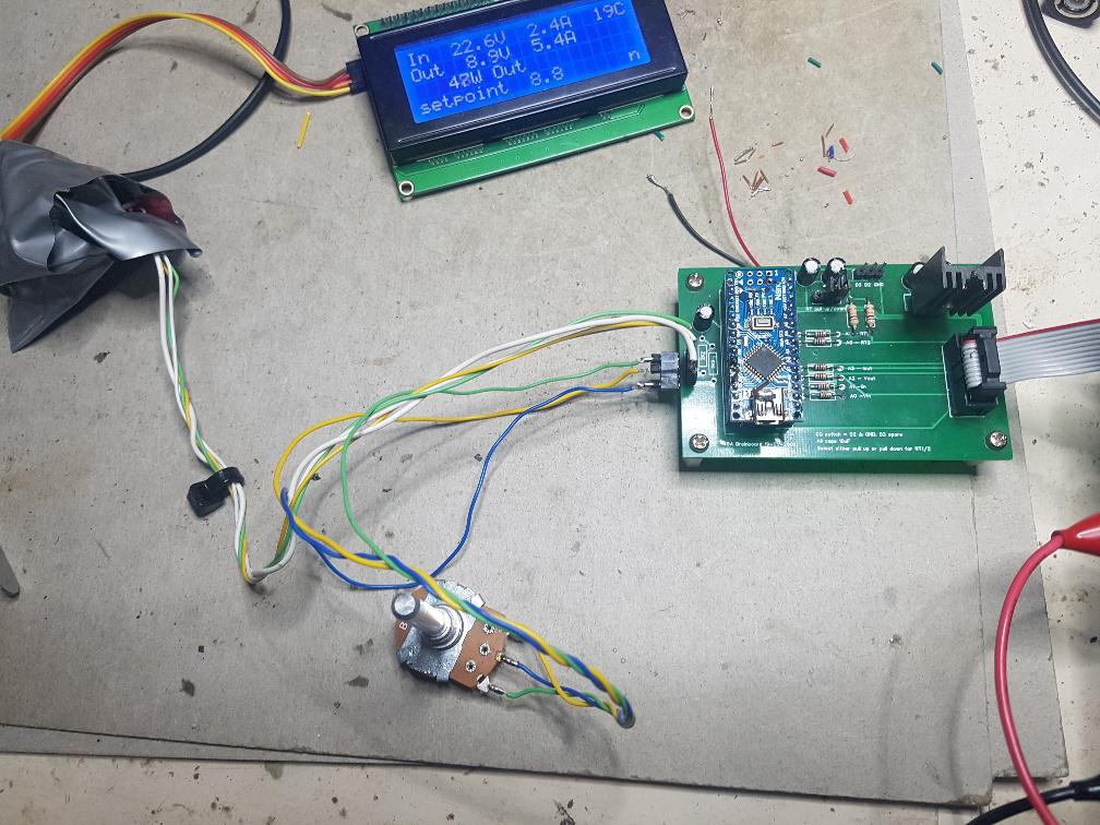 It is running, with the pot set to 8.8V on the output and the device has got 8.9V on the output. the buck converter code (like the zip file above) does not care at all about input current or output current. It just works at one thing, to make the output voltage = the pot setting. This will be good to see if your current sensors are working as you expect. Edited 2021-11-15 20:34 by poida wronger than a phone book full of wrong phone numbers |
||||
| Murphy's friend Guru Joined: 04/10/2019 Location: AustraliaPosts: 581 |
Thank you for that, I'm now almost sure its the current sensor calibration that's holding me up. I get 'G' =119 and 'H' = 118 when I do the zero sensor part of your setting up instructions. Unfortunately doing your suggested buck converter bit requires messing with programming and I have all left fingers when it comes to that. So I prefer to have somebody who knows doing that and I will ask if there is no *very* easy way to change that 119 ADC count to 127. Instructions for dummies anyone?  . .I have an oscilloscope hooked to the PWM output of the nano and was watching the narrow clock pulses you described earlier. They actually change in width, occasionally, for a whole 60 second cycle they are wider. But no current flowing in or out of the MPPT board. |
||||
| poida Guru Joined: 02/02/2017 Location: AustraliaPosts: 1388 |
How to get you going with this.. No programming needed. I have two concerns. #1 is that the output current sensor is wired in a way that increasing current gives a smaller output signal. Should this be the case then the mmpt scan will decide it's not worth running the converter and stay in night mode. We can verify that the current sensor is correct using a power supply of some sort and the DMM. If no power supply with a current limited to about 5 or 10 Amps is available we must make one. A 12V battery, one headlight globe of 60W or something. Disconnect both solar array input and the battery bank. We don't need or want this at all. First, connect the DMM to the sensor output (solder a temporary wire if needed) and ground. We will see about 0.5V when the board has 12V supply and with no current passing through the sensor. Then connect battery positive to the current sensor terminal that goes to the inductor. Connect the other side of the sensor (the Battery+ terminal) to the headlight globe, then the other globe terminal to the 12V negative. We have some current flowing through the sensor in the + direction. We should see the DMM show an increase from the 0.5V to maybe 1V when the light is on. If so, the sensor is hooked up correctly. If it drops below the zero current voltage, then we have the cause of our problems #2 Maybe the isolated 12V supply is not existing. Prove that it is on the two pins of the opto coupler. If not, then that is the problem. #3 Maybe you are using the not-connected pin on the opto coupler. Some of them do NOT join pins 6 and 7 together. My recent power supply project caught me up with this. I assumed the opto output was on pin 7. It was not. Nothing was on pin 7 I had to bridge pin 6 and 7 to make it work. Maybe you have done the same? It's one thing to know PWM is present on the opto's inputs and at sufficient current to light the diode within. It's another thing entirely to have the opto's output connected to the FET's Gates. Maybe prove that is good too? wronger than a phone book full of wrong phone numbers |
||||
| Murphy's friend Guru Joined: 04/10/2019 Location: AustraliaPosts: 581 |
OK, While I have been sitting here watching that CRO trace something in the nano woke up and the pulse tops are up to 50us wide at times. Output power shown is around 55W and 1A Iout which tallies with the battery voltage. I ran the batteries down a bit before that to entice charging but that is quite poor at present. How much charge current could I expect with nearly full width PWM pulses? I'll add my schematics below:   |
||||
| Murphy's friend Guru Joined: 04/10/2019 Location: AustraliaPosts: 581 |
Thank you for those very good suggestions. I did the 'E' and 'F' cal. amps set up with 8 Amps flowing through the allegro sensors in the right direction. I used the nano display to show that, did not think of measuring the sensor output voltage directly but will do that next. Pin 6 @ 7 of the FOD3182 are linked by a PCB track. I did look earlier at the mosfet gates and saw nothing, I just looked again and still nothing, what should I see there when its MPPT ing? There is 15.9V at pins 5 to 8 of the FOD3182. |
||||
| poida Guru Joined: 02/02/2017 Location: AustraliaPosts: 1388 |
The Gate should show about 15V pulses compared to the FET's Source pins which is the inductor connection. You can not and must not use DC ground as a reference for the Gate pulse measurement/probing. If you do you will short the solar array input positive to ground and bad things will happen. Lucky you have a small hand held CRO so it can have it's ground lead connected to the FET source pins (pin 3, right most pins) and then see the voltage applied to the Gates. These pulses should be nearly the same as the pulses coming out of the nano only not 5V, but 15V wronger than a phone book full of wrong phone numbers |
||||
| Page 1 of 2 |
|||||
