Notice. New forum software under development. It's going to miss a few functions and look a bit ugly for a while, but I'm working on it full time now as the old forum was too unstable. Couple days, all good. If you notice any issues, please contact me.
poida Guru Joined: 02/02/2017 Location: AustraliaPosts: 1388
Posted: 09:05am 16 Nov 2021
Copy link to clipboard
Print this post
good. This rules out #3 in my list of worrieswronger than a phone book full of wrong phone numbers
poida Guru Joined: 02/02/2017 Location: AustraliaPosts: 1388
Posted: 09:11am 16 Nov 2021
Copy link to clipboard
Print this post
With this 8 Amps, I want to see the LCD show something like 8 Amps Any large number will do for now, but I guess you have already calibrated it to some degree.
And one more thing: You can choose a mode of operation while in the menu. You can choose "calibration" mode. This will disable PWM and mppt search etc. to just run while showing the voltages and currents and temperatures. Make sure that is not enabled too, next time in the menu.wronger than a phone book full of wrong phone numbers
poida Guru Joined: 02/02/2017 Location: AustraliaPosts: 1388
Posted: 09:19am 16 Nov 2021
Copy link to clipboard
Print this post
AS a rough guide the mppt will find the best input voltage that gives the highest output power and run at that. It depends on the input voltage/current/power and the battery voltage and the battery target voltage.
In my case my battery needs only 10 Amps or so to take it from 52 to 54V when it is nearly 100% charged.
Lithium probably will need a lot more than that to bring it up from 52 to 54V
The mppt controller will not produce an output much more than the target voltage. Maybe 0.1V more now and then.
At 3pm at your place I expect maybe 90V and 10 Amps (if cloudy) as a possible max power. That's 900W, or about 18 Amps at 50V output. Efficiency will be 92 to 95% most of the time.
The mppt is basically a power IN = power OUT minus 5% sort of device when it has a load that keeps the output voltage lower than the target voltage.wronger than a phone book full of wrong phone numbers
Murphy's friend Guru Joined: 04/10/2019 Location: AustraliaPosts: 582
Posted: 07:18am 17 Nov 2021
Copy link to clipboard
Print this post
Its working now, simple problem but it took a while to find. I blame old age and reduced eyesight for selecting a 2K7 instead of a 270R resistor in series with the FOD3182 LED.
Still have to re calibrate the current sensors, they show around 3 times of what's actually the charging current. Their output is in the correct (going positive) direction though
I'll let it run like this on the bench for a while.
A question: the fourth line shows MPPTxx, the Absorb voltage, then a 3 digit number that changes up or down a little (what does that indicate?) and last are 3 dashes.
poida Guru Joined: 02/02/2017 Location: AustraliaPosts: 1388
Posted: 08:24am 17 Nov 2021
Copy link to clipboard
Print this post
beauty! I was beginning to wonder where you are and a visit to just get it working.. (oh, W.A. A $2K flight one way...) But it was the low current drive to the opto-coupler diode.
Recalibration of current sensors is very important. Do you have a cheap DC current clamp meter such as a Uni-T UT210E. Quite useful. But there are other ways to calibrate (see previous posts)
The 4th line shows with the 3 digits the PWM width in clock pulse units. It's not important for anyone really, but I liked to see it.
the last 3 dashes show when it's in MPPT mode. Once the battery gets up to near the target voltage, it changes to ABSORB and then it shows the absorb time or FLOAT time.wronger than a phone book full of wrong phone numbers
Murphy's friend Guru Joined: 04/10/2019 Location: AustraliaPosts: 582
Posted: 10:21am 17 Nov 2021
Copy link to clipboard
Print this post
Yes, I'm sure you would enjoy that expensive visit to Perth , you could even leave your mask back home (if they let you in) .
I do have a reasonable clamp meter, it does AC and DC current which I used for the current measurement.
A somewhat different method (than a fence wired brick in a bucket of water) is used for a high current load, in case you are interested: A big 12V lithium battery powers a cheap 12V inverter. I select the 12V current by plugging in different 230VAC light globes. A 100W flood light gives me 8Amp at battery voltage. I could even fine tune that with a Variac.
Thank you for the 4th line info, I'm the curious type if you didn't guess that already.
Murphy's friend Guru Joined: 04/10/2019 Location: AustraliaPosts: 582
Posted: 10:05am 19 Nov 2021
Copy link to clipboard
Print this post
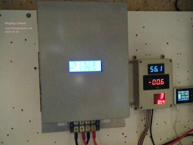
Mounted on the wall and working now. Here is what it looks like:
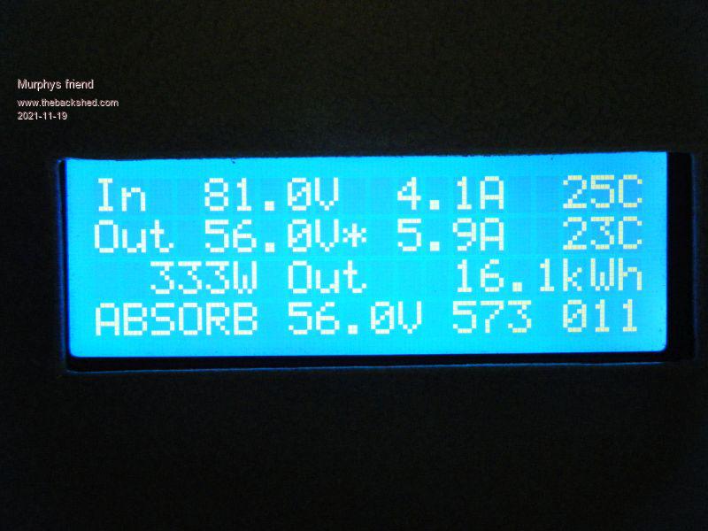
A closeup of the display, late afternoon and only a small charge going in my batteries:
Now I have to wait for a hot sunny day to see how it *really* performs
poida Guru Joined: 02/02/2017 Location: AustraliaPosts: 1388
Posted: 09:21pm 19 Nov 2021
Copy link to clipboard
Print this post
This is good to see.
When it gets some sun and a battery in need of a charge, it will put out up to 45 Amps until: 1 - the battery voltage gets to the target voltage 2 - the heat sink gets too hot and it needs to reduce current 3 - not enough coming from the panels
Further details of what is shown on the LCD.
The star next to the output voltage means the controlling is due to battery voltage being equal to the target voltage.
You might be lucky soon to see instead a star next to the output current, this means output is now limited by the max current setting, 45 Amps.
If instead you see a '!' next to the output current, then the heat sink temperature is very high and it is now limiting the output current.
I forget if you have built fans in this. But when the heat sink has the fan commanded to be running you will see a star in front of the heat sink temp. Same for the toroid temp.wronger than a phone book full of wrong phone numbers
Murphy's friend Guru Joined: 04/10/2019 Location: AustraliaPosts: 582
Posted: 07:20am 20 Nov 2021
Copy link to clipboard
Print this post
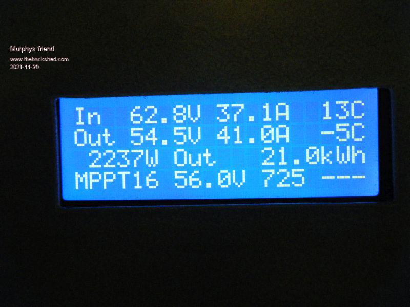
Thank you for that info Poida, I was wondering what that star meant. Here is what I got this morning, I think I can add another 500W of solar panels before reaching the 50A current sensor limit (I set 'L' to 50.00) .
You may notice the low temperature readings, these had me confused until I worked out the sensors read backward. I replaced the thermistors with 10K trimpots, at 10K I get around +25 degree displayed. Reducing the trimpot resistance (as a NTC sensor does when it gets hot) shows a decline of the temperature readout. The heatsink got barely warm with the 42Amp current.
Following the thermistor connections on your schematic was not easy and I am wondering why there is a choice of the pull up or down connection. I'm sure you had a reason but I can't think of it. To me, connecting one side of the thermistor to ground and pulling the other side up via a voltage divider would be all the program requires?
You can see on the schematics I posted earlier how mine is wired, I set '3' on the menu to 0. Please advise what I did wrong so I can get that temperature readout show the real thing.
You also mention a "fan ON and fan OFF temp setting in the menu which I left as your default settings. BTW. I cannot find how you drive the fan on your schematic so I run mine independently of the nano with its own fan control module (this has its own NTC sensor as well).
poida Guru Joined: 02/02/2017 Location: AustraliaPosts: 1388
Posted: 10:17am 20 Nov 2021
Copy link to clipboard
Print this post
The 10K NTC thermistors according to your schematic have one wire going to ground. That means "3" menu needs to be 0 (zero) If you have that in place already and you see -5C then something is wrong. No idea what right now. It's always best to play with the NTC inputs with a 10K pot and see how it performs to get a feel for it. 8.2K = 30C 6.7K = 35C 5.6K = 40C 3.9K = 50C
50 Amps is for sure no problem.
If the voltage and current inputs are calibrated well, maybe to the nearest 0.2V and 0.2 Amps then this mppt controller is doing a good job of converting the 62.8V at 37.1 Amps input into something the battery can handle.
62.8 x 37.1 = 2330 Watts input 54.5 x 41.0 = 2235 Watts out efficiency is output / input which is 2235/2330 = 96% Only 4% is lost as heat 95 Watts heat, distributed across the inductor and heatsink mainly
In your case there is no fan control from the firmware so we can forget about that stuff I mentioned above. It's up to your separate fan control system.
But the heat sink temp could cause the output current to be reduced should it get hot enough. It depends on your settings for "A" and "4" "A" is the max HS temp and should it get to that, output current limit will be limited down to zero. "4" value is where the output current starts to be reduced from 50 Amps.
So you maybe give a value of 50 deg C for "4" and maybe 65 deg C for "A" This will mean output current will start to be limited to less than 50 Amps at 50 C and by the time it gets to 65 C output current will be limited to zero Amps.
I made the brainboard able to handle NTC connected to 5V and to ground selected via a jumper because Nicks board has the NTC connected to ground and Wiseguy's boards have them connected to 5V The brainboard had to handle both cases. My 2 mppt controllers use Nicks' boards Edited 2021-11-20 20:29 by poidawronger than a phone book full of wrong phone numbers
wiseguy Guru Joined: 21/06/2018 Location: AustraliaPosts: 995
Posted: 02:52am 21 Nov 2021
Copy link to clipboard
Print this post
Where the two thermistor locations are on my PCB, there are 3 pads, if you use the two pads located within the yellow square labelled as +5 then the thermistors are connected to +5V and as Peter stated you have to use the correct menu option and link the two 10K resistors as pull downs on Peters board.
However if you install the thermistor using the centre of the 3 pads and the pad just adjacent outside the yellow square then the Thermistor is connected to Ground and will behave just likes Nicks board, that is you use the two 10K resistors on Peters board (P4) as pull ups.
When I looked at your schematic Murph it appears that you also have thermistor pull ups on your power board. I think they should be removed, as with links on Peters brain board in either position or even with the link removed, all combinations will result in misleading temperature readings ( the link removed will give almost normal results with a bit of error). The best solution is to remove the two pull ups for the thermistors on your power board. If that is too difficult to do, then removing either R8 or R9 on Peters brain board and not installing the P4 link or removing both R8 & R9 & then it doesnt matter if the link is installed or not in either position, should get your temperatures reading correctly. Edited 2021-11-21 12:59 by wiseguyIf at first you dont succeed, I suggest you avoid sky diving.... Cheers Mike
Murphy's friend Guru Joined: 04/10/2019 Location: AustraliaPosts: 582
Posted: 04:11am 21 Nov 2021
Copy link to clipboard
Print this post
Thank you for that input wiseguy. FYI, I made my own PCB's and there is NO thermistor connection or track for them on the power board at all. The thermistors plug straight into my (own style) brain board where the pull up resistors are also located.
I did not like the 10 way ribbon cable idea so all my brainboard inputs are via individual shielded cables. The thermistors are re cycled ones at the moment but I also have new ones and will try them out shortly. BTW, I did like your PCB power board layout and mostly copied it (minus the 10 way ribbon cable socket) .
I got confused by that odd way to connect the thermistors, it was obviously done to suit some else's thermistor arrangement as well. When I did my brain board artwork I was not yet fully aware why that system was used.
wiseguy Guru Joined: 21/06/2018 Location: AustraliaPosts: 995
Posted: 04:34am 21 Nov 2021
Copy link to clipboard
Print this post
Aha. I should have looked at your schematic more carefully - I didn't realise that you had made your own brain board as well. Have you fixed the temperature errors yet or is it still a work in progress ? I would be interested to know what caused the issue.If at first you dont succeed, I suggest you avoid sky diving.... Cheers Mike
Murphy's friend Guru Joined: 04/10/2019 Location: AustraliaPosts: 582
Posted: 04:49am 21 Nov 2021
Copy link to clipboard
Print this post
Yes, its fixed now. Cause? another senior moment at the menu inputs . Enough said
This MPPT rocks. I saw 50Amps charging this morning, over 2.7KW! Heatsink barely warm to touch, now with the NTC's reading correctly I get more accurate figures next full sunshine morning. It looks like the fan might get bored doing nothing in this unit. The 1oz PCB tracks also have no problem with the 50 Amps, thanks to that good layout wiseguy .
poida Guru Joined: 02/02/2017 Location: AustraliaPosts: 1388
Posted: 10:25am 21 Nov 2021
Copy link to clipboard
Print this post
good hear this further progress, again.
With the massive heatsink you have used, I suspect it's just a matter of learning how your build works during a day of good sun and solid charge currents.wronger than a phone book full of wrong phone numbers
Revlac Guru Joined: 31/12/2016 Location: AustraliaPosts: 961
Posted: 12:25pm 21 Nov 2021
Copy link to clipboard
Print this post
Nice work Murph, Also The explanation that Peter and Mike have posted is great and will help in completing the one I'm working on.Cheers Aaron Off The Grid
Murphy's friend Guru Joined: 04/10/2019 Location: AustraliaPosts: 582
Posted: 02:21pm 21 Nov 2021
Copy link to clipboard
Print this post
Thank you Aaron, I wish I had those explanations before I started but then I probably would not have learned as much about what makes a MPPT tick.
Murphy's friend Guru Joined: 04/10/2019 Location: AustraliaPosts: 582
Posted: 03:52pm 05 Feb 2022
Copy link to clipboard
Print this post
Not much happening on this forum lately so I though you might be interested what's happening with my MPPT project.
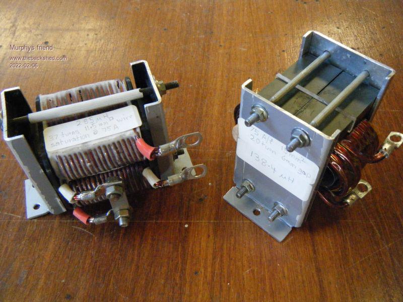
Well, its working but observing it on hot days shows that ferrite choke is getting too hot for my liking. As heat = wasted power I was thinking of ways to improve that choke.
All my inverters use re cycled (re wound) Aerosharp chokes, these use silicon steel sintered cores that come in two halves and resemble a straight side O when put together.
There are two sizes, I used the core from the smaller type and re wound it with 2.75mm wire salvaged from a bigger Aerosharp choke.
The final result is a lot better than the original ferrite choke. It only got a max of 5 degrees hotter than the heat sink (at 36 degrees ambient) while the ferrite job got more than 10 degrees hotter at similar power levels (40Amps).
So just in case anybody is interested here is my choke making lesson 101:
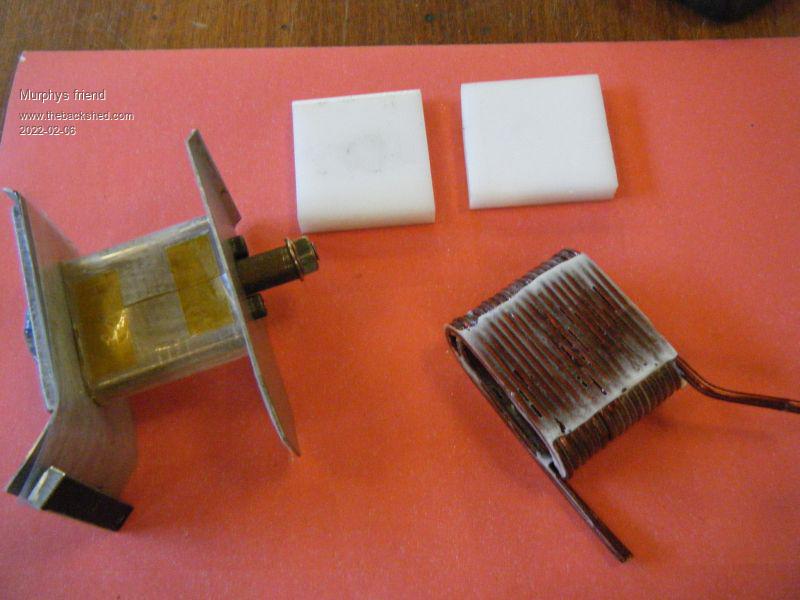
First one needs a very sturdy former to wind the wire on. All metal construction ios best but metal for the center part is not easy to shape so I used hardwood (Jarrah) with dowel halves glued to the ends. That thick wire needs to be hammered flat each half turn so its very important the center does not indent or the finished coil will get stuck on it. I also make that center 1/2mm wider on one side so, when extracted correctly, it slides out easy without too much coil destroying force being applied.
The above picture shows the former, the plastic clamping blocks and a finished epoxied coil. Note the sides and center are lined with mylar sheet cut to size. This is waxed too to stop the epoxy sticking to it.
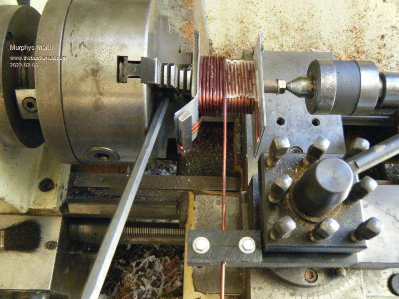
Here is how I wind them.
That thick wire cannot be wound by hand so it is done in my lathe by turning the chuck by hand (with that hexagonal rod visible between the chuck jaws). I set the carriage for screw threading with a pitch close to the wire diameter - 3mm in this case. So the wire goes on half a turn at a time, hammering it flat with a hardwood dolly & hammer each time.
When a full layer is on the waxed clamping blocks are applied and the gap between them & the wire soaked with epoxy. (don't forget a drip sheet on the lathe bed).
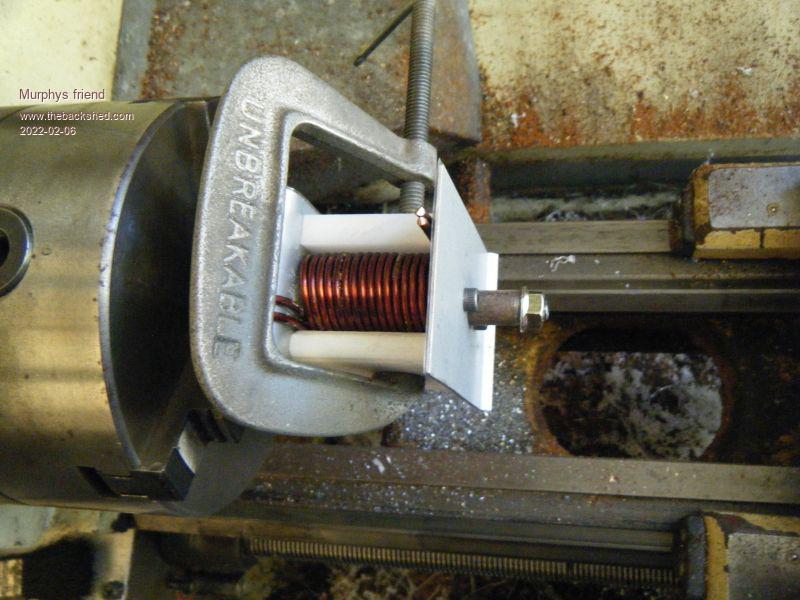
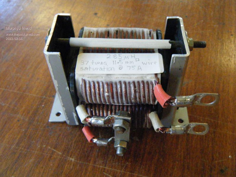
I made two coils of 18 turns each, one for each side of the core. They were first connected in series which gave me lots of inductance but required 2x1.5mm gap spacers for a reasonable saturation (75Ah). This picture shows the new choke on the left with the original ferrite job on the right. Note the Aerosharp choke is more compact too.
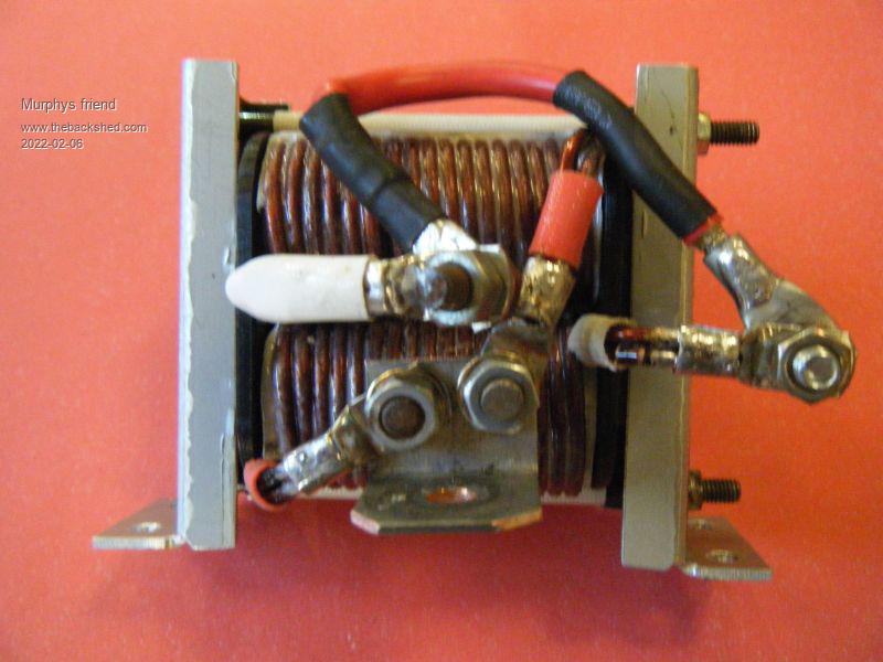
A close up of the coil series connection.
It turned out this choke still got too hot for my liking so I connected the coils in parallel which was a bit trickier.
This arrangement hit the jackpot and I'm happy with it. Specs are: 18 turns of 23mmsq wire, 145uH with 2x 0.75mm gap spacers and also 75Ah saturation.
Warpspeed Guru Joined: 09/08/2007 Location: AustraliaPosts: 4406
Posted: 10:08pm 06 Feb 2022
Copy link to clipboard
Print this post
Excellent work Klaus Cheers, ĀTony.
poida Guru Joined: 02/02/2017 Location: AustraliaPosts: 1388
Posted: 10:00am 08 Feb 2022
Copy link to clipboard
Print this post
home made thermal paste. only two cheap components glycerine and alumina https://youtu.be/8RJ-vLLwDPU?t=1259 Just in case it's an End of the World Thing and we need good thermal paste...wronger than a phone book full of wrong phone numbers


 , you could even leave your mask back home (if they let you in)
 .
.
 .
. another senior moment at the menu inputs
  .
.