
|
|
Forum Index : Microcontroller and PC projects : VGAMite V5.07.00 alpha releases
| Author | Message | ||||
| Mixtel90 Guru Joined: 05/10/2019 Location: United KingdomPosts: 7889 |
Unplug. Hold down boot0 (nothing else). Plug in USB. keep boot0 held for a second or more. Release boot0 Done Run STM32CubeProgrammer. Select USB, you should see the serial number and then connect. Cube says "No DFU detected" and there is nothing detected for the target. Tried the update button and nothing changed. Just tried the other method: plug in. Blue pulses. Hold down BOOT0. Press NRST & release. Release BOOT0. This seems to be a recommended way on the forums - but it's no different in result! I've used Cube to program my CMM2, yeah. I think I've used all three methods at one time or another. :) Mick Zilog Inside! nascom.info for Nascom & Gemini Preliminary MMBasic docs & my PCB designs |
||||
| fred777 Regular Member Joined: 01/07/2021 Location: United KingdomPosts: 57 |
Finally, found black pill at bottom of drawer, loaded bin, wired up vga & keyboard and it works! Great, finally I can put that board to work! Cool! Starting extensive testing... :-))) |
||||
| matherp Guru Joined: 11/12/2012 Location: United KingdomPosts: 10273 |
Excellent news - looking forward to the bug reports  but it's no different in result! Do you have anything connected to the blackpill? You should have just the bareboard and the USB. In particular UART pins held high can put the bootloder into a different mode. Also critical is PB2. This MUST be unconnected. If you have a PS2 keyboard connected it will not go into DFU mode Edited 2021-11-29 04:48 by matherp |
||||
| Mixtel90 Guru Joined: 05/10/2019 Location: United KingdomPosts: 7889 |
Nope, nothing. I'll double check for solder bridges on the pins before I go further. Update: Pins seem to be ok. This is a version with a flash chip on it so I've put a 10k pull-up on PA4 to 3v3 to disable it. Didn't make any difference though. Edited 2021-11-29 05:09 by Mixtel90 Mick Zilog Inside! nascom.info for Nascom & Gemini Preliminary MMBasic docs & my PCB designs |
||||
| fred777 Regular Member Joined: 01/07/2021 Location: United KingdomPosts: 57 |
So could we use a different pin for the keyboard then? |
||||
TassyJim Guru Joined: 07/08/2011 Location: AustraliaPosts: 6271 |
No problems getting mine running. I do have the one with the flash chip. Hold boot0, plug it in to the USB, start Cube programmer. I just have to get the VGA monitor back from the shed... Mild moment of panic when I went to update to a1 until I realised I was trying to use the console port instead of the USB to do the update. It's too early in the morning here. 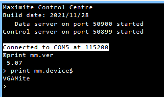 Jim Edited 2021-11-29 06:02 by TassyJim VK7JH MMedit |
||||
Grogster Admin Group Joined: 31/12/2012 Location: New ZealandPosts: 9596 |
I've ordered some blackpill modules(no flash), but I have to wait for them to arrive before I can play with anything. Watching this thread with interest though. I might rustle up a PCB with VGA socket and uSD socket etc while I wait for the modules to arrive. My PCB will allow you to select between RGB for the VGA output, but in all honesty, I've only ever used green for these kinds of thing. Green is easy to see. Selecting a red or blue text is much harder to read. Can the VGA output drive more then one of the colour inputs to the VGA monitor? If it can, jumpers to select different primary colour arrangements would be a good idea, but if it can't drive more then one colour channel to the VGA monitor, I'd probably just stick with hard-wired green only. Smoke makes things work. When the smoke gets out, it stops! |
||||
| Mixtel90 Guru Joined: 05/10/2019 Location: United KingdomPosts: 7889 |
You should be able to get away with almost full red with a bit of green to get an amber display, I think. A bit of fiddling with the values should get a similar load on the port. That could look pretty. Not sure about white as you might need rather a lot of drive. I'm not sure what the BP can handle. Mick Zilog Inside! nascom.info for Nascom & Gemini Preliminary MMBasic docs & my PCB designs |
||||
| phil99 Guru Joined: 11/02/2018 Location: AustraliaPosts: 2626 |
"Can the VGA output drive more then one of the colour inputs to the VGA monitor?" On Geoff's ASCII terminal I used an NPN emitter follower to allow it to drive all colours. |
||||
| Turbo46 Guru Joined: 24/12/2017 Location: AustraliaPosts: 1641 |
The original mono Maximite could drive all three colours. Both processors have a maximum current output of +/-25mA so I would have thought that the black pill should be capable of driving all three colours. Unless there other constraints? Anyway retro green is fine with me. Bill Keep safe. Live long and prosper. |
||||
| TassyJim Guru Joined: 07/08/2011 Location: AustraliaPosts: 6271 |
I intend to try amber instead of green. Remove the 120 ohm resistor. Use 680 ohms from the pic pin to green and 270 - 330 ohms from the pic pin to red. The diodes shouldn't be needed with those values but can be used for each channel 'just in case'. The 75 ohm impedance of the monitor should keep the levels below 0.6 volts. For white, three 330 ohm resistors to r, g & b should be OK With those values, the load on the pic pin is close to the original 120 ohms. I was going to try that today but it will have to wait a day or two. Jim Edited 2021-11-29 10:47 by TassyJim VK7JH MMedit |
||||
| gadgetjack Senior Member Joined: 15/07/2016 Location: United StatesPosts: 169 |
I am having the same problem of board not showing up. I tried what was to induce boot up but nothing shows. Tried 3 different computers and even re-loaded stm32cube program. This worked for all the other boards I had loaded basic to. I must have a bad board. Got the only one sold in the states so now it's china time I guess. Ebay will set me back 3 weeks or so....dang. |
||||
| gadgetjack Senior Member Joined: 15/07/2016 Location: United StatesPosts: 169 |
Ok , update. I remembered I had a clone ST-LINK V2 in my junk drawer. I figured I had plenty of time waiting for another board , so , I tried it. Loaded first time prefectly!!! Now I will wire it up for the vga and keyboard connector tomorrow. Also the sd card slot. Not sure why the usb didn't work but happy it is up now. |
||||
| Grogster Admin Group Joined: 31/12/2012 Location: New ZealandPosts: 9596 |
Owwww - that's a clever idea, and so simple.  Did you just use a 75R emitter-ground resistor for the load? Did you have one NPN per colour channel, or just one NPN driving all three? Your post would seem to suggest just one NPN driving up to all three... @ Jim: Yes, Amber is a nice compromise too. I still remember some ancient old WYSE terminals I used to repair that had amber CRT's, and they were quite easy on the eyes too, so perhaps..... If I put the RGB jumpers after an emitter-follower, then we could drive all three colour signal lines in any combination you want. I think that will have to be the plan. Would probably want to use the clamping diodes for that arrangement I guess. Smoke makes things work. When the smoke gets out, it stops! |
||||
| robert.rozee Guru Joined: 31/12/2012 Location: New ZealandPosts: 2440 |
this could be fun: https://nz.rs-online.com/web/p/digital-potentiometers/1904770 DS3904U-020+, Digital Potentiometer 20k 128-Position Linear 3-Channel 8 Pin, uSOP in software you could then change the colour to match ambient lighting, etc  note: i've done absolutely NO research on the suitability of the part, or what sort of buffering would be required. it may well not even be able to operate at the required frequencies (the solution may require building three variable clamps). cheers, rob :-) |
||||
| phil99 Guru Joined: 11/02/2018 Location: AustraliaPosts: 2626 |
@Grogster Here is what I used. 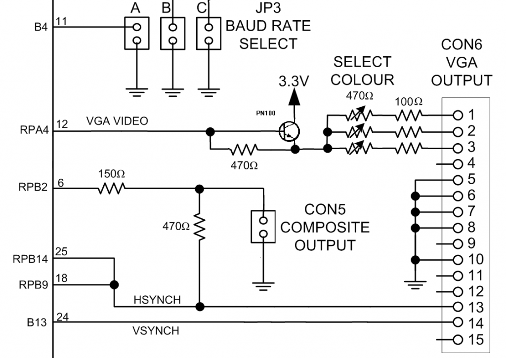 |
||||
| Turbo46 Guru Joined: 24/12/2017 Location: AustraliaPosts: 1641 |
@Grogster Not sure if Peter plans to include an external RTC but it would be a handy addition. Bill Keep safe. Live long and prosper. |
||||
| phil99 Guru Joined: 11/02/2018 Location: AustraliaPosts: 2626 |
Analogue software colour control might be as easy as using 3 PWM signals to shunt signal from the three VGA colour pins. Rudimentary colour graphics done by changing the colour mix between graphic commands. 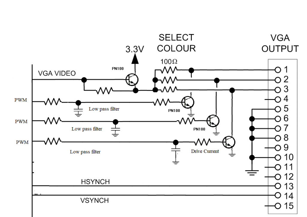 |
||||
Cyber Senior Member Joined: 13/01/2019 Location: UkrainePosts: 161 |
This is great! Ordered my Blackpill just now, can't wait to try it out. ) Almost all these pins are on the same side of the board except for PS2 clock pin (PB2). Even with this arrangement it is very good! But is there any chance to use different pin for PS2 clock, so VGA, KBD and COM would all be connected on the same side of the board? |
||||
| Mixtel90 Guru Joined: 05/10/2019 Location: United KingdomPosts: 7889 |
Why not go the whole hog, use three digital pots driven by a Micromite which is connected to the VGAmite over an I2C channel? You'd be able to switch the Micromite into 70's disco mode too! [/Decidedly_tongue_in_cheek_answer] =========================================== I've ordered another board (without flash - I don't want to wait this time) just in case I can't get to the bottom of this. Annoying that I could get two Picos for about the same price! The BP isn't all that cheap in the UK. Edited 2021-11-29 17:53 by Mixtel90 Mick Zilog Inside! nascom.info for Nascom & Gemini Preliminary MMBasic docs & my PCB designs |
||||
| The Back Shed's forum code is written, and hosted, in Australia. | © JAQ Software 2025 |
