Notice. New forum software under development. It's going to miss a few functions and look a bit ugly for a while, but I'm working on it full time now as the old forum was too unstable. Couple days, all good. If you notice any issues, please contact me.
Murphy's friend Guru Joined: 04/10/2019 Location: AustraliaPosts: 582
Posted: 09:03am 28 Nov 2021
Copy link to clipboard
Print this post
What would the display show if there was a program shut down due an over/current/ temperature/ voltage? Reason for asking is that I was greeted twice by a plain blue screen with no info showing. Both times happened after the unit was passing more than 40 amps, about 2.5Kw when I looked last. Load was two aircon's and two fridges and some low power stuff. Fairly warm day here, about 32 degrees in my shed where the MPPT is located.
On both times I got it going again by resetting the brain Nano.
After the first event I lowered the fan trigger threshold to about 45 degrees, the fan was running before the second event with heatsink & choke temperature showing a little over 40 degrees (the choke is always a little hotter as its located directly at the top of the heatsink fins).
I'm leaving the cover off for the time being, to see if its a heat related problem.
Otherwise this MPPT is performing very well, has no problem powering my house while keeping the batteries full at the same time.
poida Guru Joined: 02/02/2017 Location: AustraliaPosts: 1388
Posted: 10:07pm 28 Nov 2021
Copy link to clipboard
Print this post
Control nano: the nano that runs the mppt program and also writes serial data out of pin A4 (I think)
LCD nano: the nano that takes serial data and send it out via I2C or directly via the 4 bit bus to the LCD.
Firstly, the program does not shut down by any deliberate action within the code. It will change modes as needed, reduce output current as needed but never shut it's self down.
Next, sometimes I have seen blank screens on the second mppt I built which is all enclosed in a metal box. It was still making some current but the LCD and the nano that drives the LCD were in a blank screen state of confusion. I fixed this with a ferrite choke ring, that has the 3 wires (ground, 5V and TX) passing through it twice. This absorbs some EMI that is present and which is upsetting the LCD nano.
First question Do you recall if the mppt was still making some output current when the LCD screen goes blank?
I do not think it is heat related. I think it is EMI that is the problem.
You could put some 1uF caps across all pins that are inputs to the control nano. I see that is done from your schem.
You could put some filtering caps across the I2C pins on the LCD nano and in particular if the I2C wires are accessible run them 2 times around a ferrite choke toroid ring. These caps need to be small since the I2C bus will then have out of shape signals. Maybe just use the ferrite ring first and see if it cures things.wronger than a phone book full of wrong phone numbers
wiseguy Guru Joined: 21/06/2018 Location: AustraliaPosts: 994
Posted: 12:20am 29 Nov 2021
Copy link to clipboard
Print this post
At a guess (untried) small = 47pF - 470pF, I would expect 100pF - 220pF should do the trick, but as Poida said try the ferrite first.
Personally I have used plenty of these displays with & without serial pcb converters & seen them "go off into the weeds" or display chinese characters or gibberish when exposed to fast edge noise and never recover until power is recycled. It may be the nano going feral but it may possibly also be just localised to the LCD, either way the ferrite or/and cap filtering should help to solve the problems.If at first you dont succeed, I suggest you avoid sky diving.... Cheers Mike
InPhase Senior Member Joined: 15/12/2020 Location: United StatesPosts: 178
Posted: 05:21am 29 Nov 2021
Copy link to clipboard
Print this post
EMI... I have done lots of small Arduino projects with LCD screens and it doesn't take much noise to set one off the rails. Shielding helps a lot.
Murphy's friend Guru Joined: 04/10/2019 Location: AustraliaPosts: 582
Posted: 08:58am 29 Nov 2021
Copy link to clipboard
Print this post
Thanks guys, I'll try the ferrite ring first (if it does that blank screen trick again)
I have increased the hot air outlet openings on top of the box as well. Today I ran the MPPT without its cover, pushed the output to about 2.5KW and there were no problems. It did not get so warm either without the cover, <40 degrees all the time.
All the wiring to the nano's is shielded and as short as possible. The brain board where both the nano's are located has a full ground plane, top layer of the PCB.
What I find odd is the MPPT did its near full capacity charging thing for quite some time before the screen played up which is why I thought it may be getting too warm.
I'm not 100% sure if there was still some charging going on when the screen went blank. I know there was current flowing through the battery cables as there are Ampmeters sensing them but am not sure in which direction. The Ampmeter shows a negative sign if the battery gets charged, I will take a note of that if it happens again.
poida Guru Joined: 02/02/2017 Location: AustraliaPosts: 1388
Posted: 09:28am 29 Nov 2021
Copy link to clipboard
Print this post
The reason I want to know about the output current AND battery voltage is to determine if the control nano has locked up or not. This is the primary concern for me.
So when you get the next blank screen, note the output current, battery voltage and battery charge voltage target. We will then see if the control nano is still good, looking after your battery.
And then we look at why the LCD nano is going AWOL.wronger than a phone book full of wrong phone numbers
nickskethisniks Guru Joined: 17/10/2017 Location: BelgiumPosts: 409
Posted: 09:21pm 29 Nov 2021
Copy link to clipboard
Print this post
I have experienced it to, switching to the "serial version" solved my problem, make the wires as short as possible and run them as close to each other as you can. I got those problems above 30A, now I run 100A without problems except a lot of heat.
I made an experimental boost converter with the same problem, there I used a ferrite and that solved the problem too , powerwires need to be close to each other. If you need to have the wires apart from each other, split them only at the first/last point, run the wires as long as you can close to each other. This helps in limiting the radiation, a ferrite on the in and output should help to, driving the mosfet with higher Rgate is something I didn't test.
Murphy's friend Guru Joined: 04/10/2019 Location: AustraliaPosts: 582
Posted: 10:12am 30 Nov 2021
Copy link to clipboard
Print this post
100A from a single MPPT? You like pushing it if that is the case . I split the charging here, 3KW from grid tie inverter back charging and 2KW from the MPPT. The warpverter does not mind the back charging.
So far my new (poida) MPPT runs happily again, no upsets due to high charging currents. I did improve the ventilation of the enclosure and its now cooler in there.
I had the advantage of poida's experimenting and took on board what he experienced with 'glitches'. Having no fancy CRO to see these gremlins I made sure my PCB layout and wiring to it was, IMO, very good . So I was surprised to have the display go blank on me twice. Its going to be even warmer here in the next few days so I can push my MPPT up to close the 50A limit I set in the menu. I'll keep my fingers crossed while often checking that display .
Murphy's friend Guru Joined: 04/10/2019 Location: AustraliaPosts: 582
Posted: 04:23am 02 Dec 2021
Copy link to clipboard
Print this post
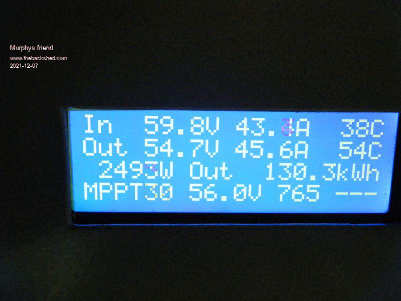
"the next blank screen" happened this morning. My MPPT was charging fine when I went out for my walk but I was greeted by the dreaded blank screen one hour later when I got back.
The battery voltage then was 56V, so my MPPT was at the absorbing state. There were still ~10A flowing into the battery bank which is about normal when absorbing. This means the brain nano was doing its job just fine, just I could not see on the display what it was doing .
I have now fitted the suggested ferrite beads and also a 10uF capacitor at the DC input to the display module.
Hopefully that fixed it
Murphy's friend Guru Joined: 04/10/2019 Location: AustraliaPosts: 582
Posted: 02:18am 03 Dec 2021
Copy link to clipboard
Print this post
So the display has just gone blank again!! This time while I was watching the display. And that despite fitting the suggested ferrite beads yesterday.
It happens just as the nano changes the charging regime from MPPT to Absorb. That occurs when the battery voltage reaches 56.00V. Charging current before the event was 41A. Choke temperature cycled between 49 degrees (fan on) and 41 degrees (fan off). Heatsink temperature was 32 degrees. The unit was still charging at over 20 Amps on my clamp meter before I reset the nanos.
Its a real nuisance having to open the case to reset the brain nano and the display nano. I'm thinking of fitting eternal reset buttons for these . Should I buy another display? If so, which one works most reliably as I have no idea how to choose from the many offered on ebay.
Revlac Guru Joined: 31/12/2016 Location: AustraliaPosts: 961
Posted: 02:55am 03 Dec 2021
Copy link to clipboard
Print this post
Murph, Is there any contact between the LCD metal case and the steel case that it is mounted in? I had to insulate one of my display's, and use shielded wire, shield connected at one end only.Cheers Aaron Off The Grid
Warpspeed Guru Joined: 09/08/2007 Location: AustraliaPosts: 4406
Posted: 03:06am 03 Dec 2021
Copy link to clipboard
Print this post
The ferrite trick usually works, BUT it needs to be real high permeability ferrite, not some anonymous compressed mud Chinese powdered iron mystery ring.
Do you by any chance have a pair of those big ferrite E65/32/27 E cores many of us are using for choke cores ? Try a pair of those, tightly taped together (no gap) with about ten turns. If that fixes it, a much smaller toroid of the right stuff should work just as well. Edited 2021-12-03 13:07 by WarpspeedCheers, �Tony.
noneyabussiness Guru Joined: 31/07/2017 Location: AustraliaPosts: 506
Posted: 05:49am 03 Dec 2021
Copy link to clipboard
Print this post
ive been having a similar issue with a temp control board I made, using a I2C screen... had a 6.3v 1000uf cap straight on board, with a .1 uf ceramic in parallel... still kept locking up randomly... so got the s#$ts and scavenged several " clamp on " ferrite noise suppressors ( lol, about 10 ) from some audio equipment I had pulled apart... have a significant distance between screen and nano ( for display) that I can't really avoid .. because the connecting cat6e cable is inside the cabinet it doesn't matter about looks so much... but 2 days now and no lockups...I think it works !!
Warpspeed Guru Joined: 09/08/2007 Location: AustraliaPosts: 4406
Posted: 06:05am 03 Dec 2021
Copy link to clipboard
Print this post
Noise suppression ferrites work best at very high frequencies, typically tens to hundreds of Mhz.
The strong harmonics coming from a PWM switching power supply may be at their worst at much lower frequencies, below 1 Mhz.
A common mode transformer needs a reasonably high inductance to work properly. Suggest you try the big E cores. If its the correct approach that will work. If it makes no difference there must be a different interference mechanism in play.Cheers, �Tony.
Murphy's friend Guru Joined: 04/10/2019 Location: AustraliaPosts: 582
Posted: 08:47am 03 Dec 2021
Copy link to clipboard
Print this post
You might have a good point there, I did not think of that possibility. The big heatsink is mounted on a 3mm alu back plate which also supports the choke & fan. The grey cover case is actually made from 1.6mm aluminium, its only painted on the outside. So its quite possible the black metal surround of the LCD makes contact with the alu cover. I actually saw the display go blank twice, when I put the cover back on. Thought I disturbed some wiring or something . That cover is screwed to the heat sink sides. I have connected an earth wire to the back plate, this goes to a ground stake that also earths the solar panel frames. All the sensor wires are shielded, ground to brainboard common. The SDA and SCL wires to the display module have 2 ferrite beads on each and these wires are only about 50mm long. The power to brain board ground is via a ferrite bead as per wiseguy's PCB layout.
Tony, as much as I would like to try your E65 core idea, its a bit difficult to do in practice. There is no room under the housing for that and I'm using that MPPT to charge my battery bank so I prefer to leave it mounted where it is now. The ferrite beads I used are some left overs I got a long time ago from RS. In their (very old) catalogue they are described as "anti parasitic" and used for "decoupling purposes". Probably not made from Chinese mud .
What I'll do now is run the thing with its cover off for a week, if the LCD does not go blank on me then I try running it with insulating tape around the inside of the display cutout in the housing.
Thank you all for your input, its very much appreciated. That MPPT has now passed the 100KWh mark and I'm happy with its performance. Charging current is about 5A more than the solar panel input and at full power its near 97% efficient.
Murphy's friend Guru Joined: 04/10/2019 Location: AustraliaPosts: 582
Posted: 10:28am 07 Dec 2021
Copy link to clipboard
Print this post
I think its fixed now. Very peculiar fault, never came across anything like it before.
The MPPT unit would run fine without its cover. Putting the cover on caused the LCD display to go blank after heavy current charging.
Aaron suggested to insulate the metal cover so it does not touch the metal frame of the LCD. Did that, made no difference.
But I noticed when I carefully replaced the cover the LCD was OK until the very final position of the cover.
So it turned out not to be an electrical connection to nor a mechanical disturbance of the LCD frame but the *proximity* of the cover to the LCD.
Simple solution, machined off 2mm from the nylon spacers that hold the LCD display module. There is now a 2mm gap between the LCD and the MPPT metal cover. This is not enough to make reading the display difficult through the cover cutout. But it made my blank screen problem go away .
My guess is that some kind of capacitive coupling upset the LCD display.
I put the unit under severe load to see if my cooling fan can keep up.
It can by the look of it, temperature in my shed was 30 degrees then. Strangely, its the choke that gets hot, more than 10 degrees over the heat sink. Its not copper losses as the 15 sq mm enameled wire should easily pass the 45 odd amps.
phil99 Guru Joined: 11/02/2018 Location: AustraliaPosts: 1779
Posted: 12:15pm 07 Dec 2021
Copy link to clipboard
Print this post
"Strangely, its the choke that gets hot" Sounds like the core material does not like the high frequency, or it is going into saturation causing larger hysteresis power loss.
Revlac Guru Joined: 31/12/2016 Location: AustraliaPosts: 961
Posted: 12:21pm 07 Dec 2021
Copy link to clipboard
Print this post
Very good, I think that might be trick. I fitted 2 of these displays in 3D printed cases that give them a few milometers clearance from the metal casing, giving it some clearance looks like that might be the way to go. Thanks for confirming.Cheers Aaron Off The Grid
Murphy's friend Guru Joined: 04/10/2019 Location: AustraliaPosts: 582
Posted: 01:15pm 07 Dec 2021
Copy link to clipboard
Print this post
I'm not sure about the frequency but they are the same cores poida used. I tested them for saturation and this occurs past 75Amps, well above the expected MPPT current, with the 20 turn coil I used. An other observation, on saturation on my tester that choke squeals loudly. In the MPPt its completely silent.
poida Guru Joined: 02/02/2017 Location: AustraliaPosts: 1388
Posted: 08:48pm 07 Dec 2021
Copy link to clipboard
Print this post
my chokes get warm, about as hot as the the heatsinks which are a lot smaller than yours. after an hour at 30 Amps, the HS will be 40C, the chokes maybe 45C
I think about 1/2 heat is from DC resistance in the choke winding and the other half being core losses. The PWM freq is 20kHz but the waveform is a very sharp squarewave so that means big current at 20kHz, 1/3 big current at 3 x 20kHz, 1/5 BC at 5x 20kHz etc. there is a lot of current at the higher frequencies and this is what is heating the core
My 2 mppt builds differ in one respect. I put the second unit in a metal case. This unit made the serial LCD freeze some times particularly when doing the mppt scan with a large input current and 1/2 discharged battery.
The fix was to run the 3 wires connecting the mppt and serial nano through a mains power lead clip on ferrite choke.
I think the huge EMI radiated by the choke and power board couple well with the metal case, causing all sorts of unplanned voltages on anything metal inside. We have a Faraday Shield with the radiation on the inside!wronger than a phone book full of wrong phone numbers


 . I split the charging here, 3KW from grid tie inverter back charging and 2KW from the MPPT. The warpverter does not mind the back charging.
 . So I was surprised to have the display go blank on me twice.
 .
.  .
.
 . That cover is screwed to the heat sink sides.