
|
|
Forum Index : Electronics : Winding Transformers
| Author | Message | ||||
Haxby Guru Joined: 07/07/2008 Location: AustraliaPosts: 419 |
IGBTs have a lot going for them in the case of a warpverter. The warpverter switches at slow speed, so older slow giant igbt modules work well in this environment. IGBTs have a constant voltage drop, no matter what current (within reason), of around 1 to 2 volts, whereas MOSFETs have an internal resistance. IGBTs have a negative temperature coefficient, so during overload, they decrease the voltage drop and hence dissipate less heat per amp (bond wires excluded). Whereas MOSFETs exponentially generate more heat internally till they cook themselves. Pretty much every motor speed controller for electric cars and scooters has used IGBTs due to their robustness. Slower switching speeds help with EMI interference too. The problem comes when using IGBTs at lower voltages. A 2V drop per igbt is a 4v drop in a H bridge circuit. That makes the switching stage of: A 400v inverter 99% efficient. A 48V inverter 92% efficient. A 12V inverter only 66% efficient. That's just the H bridge losses. Tony (Warpspeed) chose a 100v supply for his inverter, and chose giant IGBT modules for the two largest stages, and little MOSFETs for the two smaller stages. It was a good compromise of all of the variables. |
||||
| Murphy's friend Guru Joined: 04/10/2019 Location: AustraliaPosts: 592 |
Tony had those 'giant' IGBT modules sitting on his shelf waiting for a project. The double current requirement, meaning even more gigantic (expensive!) IGBT's, for the similar power of a 48V inverter makes using Mosfets in parallel a cheaper option. Has anybody seen a 48V inverter using IGBT's inside? |
||||
| Murphy's friend Guru Joined: 04/10/2019 Location: AustraliaPosts: 592 |
He does help via personal email but he's pretty busy at the moment. |
||||
| Alston Regular Member Joined: 04/04/2021 Location: AustraliaPosts: 63 |
I spoke to Tony about IGBTs and he said while he used to think they wouldn't be suitable for 48volt inverters, but having now seen the real world efficiency of his he thinks they would be perfectly suitable. There is certainly less physical complexity with his layout. I actually haven't decided which path I will go down, getting the transformers wound and designing my own control board (based around the Raspberry Pi Pico) are the first massive tasks to accomplish. |
||||
| nickskethisniks Guru Joined: 17/10/2017 Location: BelgiumPosts: 420 |
If efficiency is no concern for you, then just go for the IGBTÆs, if we consider some parameters then a mosfet bridge will be around 2mR. A bridge with IGBTÆs will have 2.4V voltage fall. With 100A going thrue the bridge this will be 20W loss for the mosfets and 240W for the igbtÆs. Considering 200A this will count for 80W loss with mosfets and 600W with IGBTÆs (3V fall). ItÆs just as rough indication, real numbers could be different, there are some switching losses which will also be higher with IGBTÆs because they are slower and have higher voltage fall. IGBTÆs would make a very simple design possible. |
||||
| Murphy's friend Guru Joined: 04/10/2019 Location: AustraliaPosts: 592 |
Agree with the simplicity argument. But the extra losses at 48V due voltage drop - not for me. Switching speed does not matter with a warpinverter. After all most of us are building an inverter to run off batteries so any extra losses are a big deal. Also consider that a bigger heatsink would be required for those IGBT's. With my warpinverter, which could possibly do 7.5KW, hearing the fan come on is very rare. Only happened on a 40+ degree C day when the aircon was running all day. Yes, its complicated with a total of 40 HY4008's, costing around $A 100.- shipped from LCSC. I doubt that 4 big IGBT's can be bought for that price. The smaller ones for the other transformers are cheaper but a total of 16 IGBT's for the inverter are required. |
||||
| rogerdw Guru Joined: 22/10/2019 Location: AustraliaPosts: 808 |
This is a very timely discussion for me at the moment and I'm really pleased to see all you guys weighing in. I'm still winding my largest toroid but have to decide how I'm going to switch it. Four layers down, three to go. I had wondered if I could use mosfets for all three smaller toroids and use a pair of half bridge IGBT's for the large one. I'm having a bit of a mental blank trying to work out what spec devices I would need. I found a couple 300A IGBT's that have a saturation Vce(on) of 1.45V ... but that's still a ~3V drop across the bridge. For mosfets the HY4008 datasheet shows them to be 200A at 80V, which surprised me. It doesn't show whether they have isolated tabs or not ... that will make a lot of difference to the construction and heatsinking. I noticed the larger OzInverters used 6 mosfets per leg of the bridge ... but as has been mentioned, the Warpverter has much slower switching. I have no idea what difference that makes, if any ... other than giving the devices an easier life perhaps. The other issue is that my large toroid is pretty big so I'm not sure how to work out what I need. I sorta recall that Tony was suggesting my primary winding may need to carry 307A ... but I assume that's only if I try to drag full load out of the inverter. Alston, you mentioned you had bought some 400A IGBT's. Do you mind telling me what part number they are please. Thanks everyone. Cheers, Roger |
||||
| Murphy's friend Guru Joined: 04/10/2019 Location: AustraliaPosts: 592 |
Roger, your large transformer is not any bigger than mine (dual stack 3KW Aerosharp cores). I'm using 4 HY4008's per bridge leg, 16 in total for that transformer. That was plenty in my experience. The tab is *not* isolated with those devices. You have basically 2 methods of heatsinking, Tony's, using 1 heatsink per half bridge and the mosfets/IGBT's directly mounted. Naturally, each of the 16 heat sink has then to be mounted isolated from the others. This makes for a rather long assembly. I isolated (using mica washers) each Mosfet, so the heatsinks were not 'life'. That way only two full size Aerosharp heatsinks were required. Placing the heat sinks fin to fin so the Mosfets fit on the outside made a much more compact assembly, the 125mm fan was mounted at one end (bottom side) with the heat sink assembly being vertical in the enclosure. Have a look at the pictures of tinkers warp inverter build. The OZ inverter used 6 mosfets per leg because back in those days we used TO220 devices. I remember having lots of trouble back then with that arrangement. |
||||
| Alston Regular Member Joined: 04/04/2021 Location: AustraliaPosts: 63 |
Roger my thinking was similar to yours of only using an IGBT for the biggest transformer. I want to do the maths and see what the actual figures would look like, although the mosfet inverter will be more efficient. The 400amp modules I got are Fuji 2MBI400U2B-060. |
||||
| rogerdw Guru Joined: 22/10/2019 Location: AustraliaPosts: 808 |
Thanks for the clarification Klaus, that certainly helps. I'm leaning towards isolating the mosfets too ... to avoid having to have multiple isolated heatsinks. Are you using the TO-3PS-3L case device? Thanks Alston, I've downloaded the datasheet to have a look. I had looked on ebay at various types and also on element14. The well known brands like Semikron etc are certainly expensive there $2-300 etc ... but element14 also have another range of Starpower devices which are much cheaper. eg a GD300HFX65C2S 343Amp 819Watts is $113.41 ... see here And their GD300HFU120C2S 395Amp 1.984kW is $ 154.13 ... here Having said all that ... seeing I'm going to be using mosfets for the smaller toroids ... I may as well use them for the large one as well perhaps. I'll be interested to hear your conclusions after you do your maths. Haxby and Nick's figures opened my eyes a bit regarding efficiency and leans me more back towards mosfets too. Cheers, Roger |
||||
| Murphy's friend Guru Joined: 04/10/2019 Location: AustraliaPosts: 592 |
Roger, the HY4008's have a TO247 case. I mount them on small sub PCB's that hold 2 mosfets. Two of these assemblies are clamped side by side to the heat sink using a 3x20mm alu backing strip and stainless M3 socket screws. You need a decent pressure for heat transfer with the mica washer insulators. Also consider their easy replacement with your design, its easy to blow them if one is not quite sure what makes this inverter tick. If you blow those expensive IGBT's instead you'd wish you had used the much cheaper Mosfets  . .There should be photo's of that Mosfet PCB arrangement somewhere among my posts. Using the big IGBT's can be an expensive alternative (unless you have them already) beside the extra losses. With your dual stack big transformer you can assume a max of 7.5KW of inverter output power. If you divide your total power drawn at any time into 40 equal parts then the big transformer contributes 27/40th of that. #2 transformer does 9/40th, #3 does 3/40th and the tiny one 1/40th of the total power. So you see the majority of output power is from the big tranny and its associated Mosfets. My practical experience is using a total of 40 Mosfet devices. 16 for #1; 12 for #2; 8 for #3 and 4 for #4 transformer. What you need to consider now, as you near finishing your winding job, is sourcing the big capacitors. They play a major physical presence in that inverter, they are BIG. I use 4 x 33,000uF/100V, Tony says a total of 150,000 would be better. But these things are expensive, sit down when you shop for them  . . |
||||
| Haxby Guru Joined: 07/07/2008 Location: AustraliaPosts: 419 |
If you choose IGBTs, make sure they have the internal diode built in. I bought some IXYS brand IXGN320N60A3 parts for my inverter and didn't think to check. So I had to add an external diode to each one, but only after blowing up a couple of them.  They are a nice form factor to work with though. Half bridge and full bridge modules come up on eBay here and there. Yes capacitors are expensive and the warpverter needs lots of capacitance, especially for longevity! I'd suggest a film capacitor across the supply right at the IGBT screw terminal pair. Similar to the film cap across the original aerosharp IGBT module. |
||||
| rogerdw Guru Joined: 22/10/2019 Location: AustraliaPosts: 808 |
Again, that's very helpful thanks Klaus. It's sorta how I expected but it's nice to have it confirmed. Haha, yeah ... had been wondering about them too. Ouch, that's gotta be painful. Thanks for the warning. I had looked at lots of different units but never having had any experience with them, have been a little aprehensive. I do recall Tony suggesting the 150,000uF value that Klaus just mentioned ... and have been looking at some 100V ones from element14. I do have a box full of 47,000uF 63V Epcos caps ... but I assume I really need a higher voltage. Thoughts? I might have to spend some time researching film capacitors too. 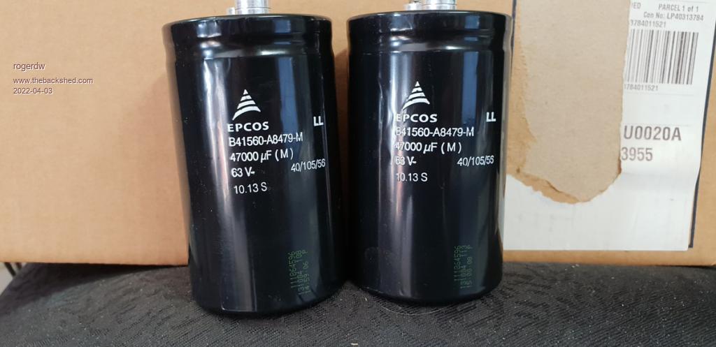 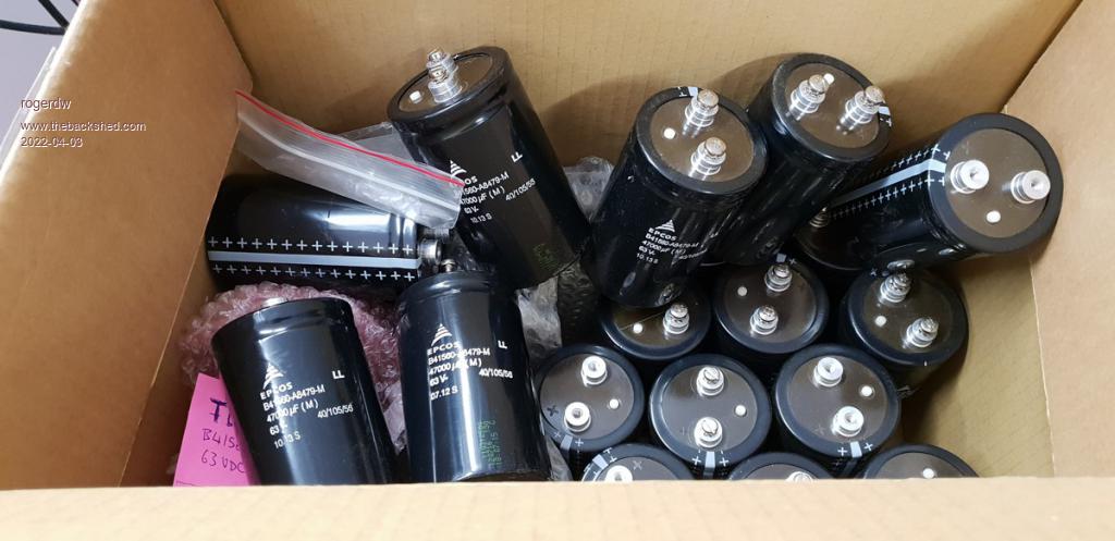 Cheers, Roger |
||||
| Murphy's friend Guru Joined: 04/10/2019 Location: AustraliaPosts: 592 |
Hi Roger, Nice to have a box full of what look new capacitors. 63V is cutting it a bit fine my charging set up goes to 56V bulk charging. However, you could connect two of these capacitors in series (with a high value bleed resistor across each to keep them at equal potential) and then connect those series pairs in parallel. It looks like you have about 12 Caps so 6 pairs would give you sufficient capacitance. I suggest you make a separate PCB (or mount them on alu busbars) so you can easily disconnect them for inverter trouble shooting. In my experience, the easier it is to isolate sections, of what is a rather complicated inverter, the easier it is to find gremlins should there be any hiding somewhere. In another thread you show your beautiful winding job has run out of wire. It's OK to use different wire as long as the turns match. I try to attach a pdf document of my winding data as I have a suspicion you are getting carried away (too much fun?) with your layers in parallel. Warpinverter transformers.pdf |
||||
| Solar Mike Guru Joined: 08/02/2015 Location: New ZealandPosts: 1128 |
Those 47,000uF 63V Epcos caps should be ok, their spec has a surge voltage of 1.15 x 63v; the max voltage you can place across them is your battery bank, so if that doesn't exceed 63v they should work fine. Their max voltage is also temperature dependent, if they run cool then you will be good to go. If they were some no-name Aliexpress with dodgy fake labels then the situation would be different... Cheers Mike |
||||
| rogerdw Guru Joined: 22/10/2019 Location: AustraliaPosts: 808 |
Yes, I found them for sale on Facebook Marketplace a year ago and couldn't pass them up. There's 24 in the box ... $200 for the lot! I did wonder about doing that ... but they're big and that ends up taking a lot of room. That makes a lot of sense for fault finding. The more of those sorts of things I can build in the better. After a lifetime of fixing things for a living ... anything I build needs to be super easy to work on. Thanks for the compliment ... I do enjoy the process in a perverse sort of way ... it is certainly satisfying to see the result when it all comes together.I need to compare my numbers with your pdf, though I didn't note the weights of my smaller toroid cores. The large core has a total cross sectional area of 93cm▓, so it does seem I got a bit carried away. I took the centre out 20mm to 120mm ... then wound heaps more on the outside and took up to 250mm OD. The secondary for this one is 6 (or 7) layers of 112T of 1.8mm and Primary 22T That's encouraging thanks Mike ... though if there's any doubt, I'd rather invest a few more dollars and build in some more head room. The brand certainly caught my attention when I saw them for sale, so was really happy to score them on the off chance I'd find a use for them somewhere. I do recall nickskethisniks had some issues with some electros failing because they were too close to the limits and perhaps not so good a quality. Cheers, Roger |
||||
| Murphy's friend Guru Joined: 04/10/2019 Location: AustraliaPosts: 592 |
That's 6 x 2.5mm sq in parallel, good for a conservative 60A or 14KW  Are you sure you need that capacity? Keep in mind the secondary wire cross section is the same in all 4 transformers, you are giving away a lot of hole space here. I was wondering why you re wound the core for a much bigger hole, now I know why. I used the standard Aerosharp toroidal core hole and used 3 x 7 strand twisted (cable lay) 1.8mm enameled wire for the primary, all fitted easily with just 3 parallel secondary windings. |
||||
| rogerdw Guru Joined: 22/10/2019 Location: AustraliaPosts: 808 |
No, probably not. In the early stages I didn't really understand what sort of power levels I might need ... and so I was looking for ways to stay on the high side ... and got a bit carried away. I do have some power hungry applications, but they are not all that regularly needed. I kinda figured that I hope to only build this thing once ... so if it's on the big side and spends a lot of its life idling along, then it should have an easy life and hopefully be trouble free. The smaller transformers all worked out okay for the same size secondary, so I didn't think too much about it. From reading of everyone elses's experience, I figured that hole size was often the cause of problems ... so I wanted to increase it to make sure I didn't run out of room ... and also allow room for the additional spacer to hopefully address the capacitace issue that Mack ran into on his early build. So then I figured I should add more to the outside to make up for what was removed from the inside ... and then got more carried away. Cheers, Roger |
||||
| Murphy's friend Guru Joined: 04/10/2019 Location: AustraliaPosts: 592 |
I too hoped to build this thing once but then ended up almost re building the electronics completely. You have a challenge ahead of you there, I found it not easy to make it reasonably compact, easy to service and reliable. Got there in the end, recent problems were caused by my experimenting with a different control board. Regarding power requirement, your battery will dictate that. Peak starting loads are no problem with anything I have here. There should be enough solar charging to get the batteries full by lunchtime latest on most days and the rest of the day power comes directly from solar, batteries are being kept full. |
||||
Chopperp Guru Joined: 03/01/2018 Location: AustraliaPosts: 1032 |
Hi Roger. Great find. By any chance you would consider selling 2 or 3 of them would you? Brian ChopperP |
||||
