
|
|
Forum Index : Microcontroller and PC projects : PicoMite: Couple of questions...
| Author | Message | ||||
Grogster Admin Group Joined: 31/12/2012 Location: New ZealandPosts: 9975 |
Hiya.  Q1: "OPTION SDCARD CSpin, CLKpin, MOSIpin, MISOpin. This allows complete flexibility over the pins chosen which do not need to be valid SPI pins" Is there any provision for the CD(Card Detect)pin on many SD sockets? I expect this could be easily dealt with with an interrupt and connecting CD to any pin, therefore not requiring firmware support - yes? Q2: How much juice can you suck from the PM 3v3 pin? I've looked at the Pico datasheet, but there does not appear to be anything in there to say what the current limit is. I have yet to look at the datasheet for the buck-boost chip used on the Pico, but that will be next. Smoke makes things work. When the smoke gets out, it stops! |
||||
| matherp Guru Joined: 11/12/2012 Location: United KingdomPosts: 11512 |
No, the firmware automatically detects card removal without needing CD. Remove a card after using it and you will see |
||||
| Mixtel90 Guru Joined: 05/10/2019 Location: United KingdomPosts: 8911 |
According to the Pico datasheet (page 8) it's recommended that the external load on 3V3 should be kept below 300mA. Maximum output capability actually depends on VSYS voltage and RP2040 load. Mick Zilog Inside! nascom.info for Nascom & Gemini Preliminary MMBasic docs & my PCB designs |
||||
| georgestheking Newbie Joined: 21/12/2021 Location: BelgiumPosts: 32 |
Hi, In the datasheet of the RT6160 regulator we read it can provide maximun 0.8 A. The RP2040 board need 0.1 A. The documentation say 0.3 A is available. A SDCARD need something like 0.1 A Best regards Georges Edited 2021-12-30 18:35 by georgestheking |
||||
| Mixtel90 Guru Joined: 05/10/2019 Location: United KingdomPosts: 8911 |
The maximum available might also depend on the heatsinking available before the SMPS shuts down on over temp. It might be rated for 0.8A but that will be under ideal conditions. There isn't a lot of space on the Pico board. I doubt very much if you could even depend on the full 300mA in all cases. Also, SMPS noise goes up with load and that could be a factor. Mick Zilog Inside! nascom.info for Nascom & Gemini Preliminary MMBasic docs & my PCB designs |
||||
| Grogster Admin Group Joined: 31/12/2012 Location: New ZealandPosts: 9975 |
Thanks everyone! I only want to use the 3v3 output, to power the SD card, the DS3231 RTC module, a LV reference for a four-channel 3v3/5v level corrector and an MAX3232 level corrector to generate the RS232 output I want. I expect all this is well within the capabilities of the Pico's on-board regulator then. @ Mixtel - Page 8. How did I miss that?! (rhetorical) Bugger. Thanks. Smoke makes things work. When the smoke gets out, it stops! |
||||
| Grogster Admin Group Joined: 31/12/2012 Location: New ZealandPosts: 9975 |
I've finally got a chance to play with my PM VGA prototype board, and as matherp said, the firmware does not need the CD(card detect) pin, and knows when you have removed the card. It responds with: "Warning: SDcard Removed" That's great, but that made me think - HOW does the firmware know the card was removed, WITHOUT a CD pin? Can Peter or anyone else in the know, explain to me how the firmware knows you have removed the SD card, without the use of the CD pin? Smoke makes things work. When the smoke gets out, it stops! |
||||
lew247 Guru Joined: 23/12/2015 Location: United KingdomPosts: 1709 |
Asking this here instead of opening a new topic Can anyone glance this over and tell me if I have it correct please? ILI9341 display with touch and Picomite 5v VBUS GND GND CS GP17 RES GP20 D/C GP21 SDI GP19 SCK GP18 LED GP22 SDO GP16 T_Clk GP18 T_CS GP15 T_DIN GP19 T_OUT GP21 T_IRQ GP14 OPTION SYSTEM SPI GP18, GP19, GP16 OPTION LCDPANEL ILI9341, L, GP21, GP20, GP17, GP22 OPTION TOUCH GP15, GP14 |
||||
| Volhout Guru Joined: 05/03/2018 Location: NetherlandsPosts: 5931 |
According to the manual, when you declare SYSTEM SPI, this SPI bus is used for Touch, ILI9341 and SD card combined. These devices share clock, MISO and MOSI pins, but have individual CS and INT pins (and D/C for te ILI9341). In that case: ILI9341 ------------- OPTION LCDPANEL ILI9341, OR, DC, RESET, CS The backlight PWM channel driving the LED, is not part of the OPTION LCDPANEL decaration. It must be declared in a separate line. (GP22 must be removed). GP22 is a genuine PWM pin (PWM3A) so the wiring can be done. But declaration must be separate.. Touch --------------- T_Clk = GP18 (correct) T_CS = GP15 (correct) T_DIN = GP19 (correct) T_OUT = GP16 T_IRQ = GP14 (correct) Regards, Volhout Edited 2022-03-04 00:15 by Volhout PicomiteVGA PETSCII ROBOTS |
||||
| lew247 Guru Joined: 23/12/2015 Location: United KingdomPosts: 1709 |
So I not need T_out connected on the ILI9341? GP22 is PWM0B why can't I use this? The manual says Backlight Control For the ILI9163, ILI9341, ST7735, ST7735S, SSD1331, ST7789, ILI9481, ILI9488, ILI9488W, ST7789_135 and ST7789_320 displays an optional parameter ', backlight' can be added to the end of the configuration parameters which specifies a pin to use to control the brightness of the backlight. This will setup a PWM output on that pin with a frequency of 1KHz and an initial duty cycle of 99%. You can then use the BACKLIGHT command to change the brightness between 0 and 100%. The PWM channel is blocked for normal PWM use and must not conflict with the PWM channel that may be set up for audio. For example: OPTION LCDPANEL ILI9341, OR, DC, RESET, CS, GP11 The backlight can then be set to 40% with this command: BACKLIGHT 40For the SSD1963 displays the backlight is controlled by the SSD1963 controller chip using the BACKLIGHT command |
||||
| Volhout Guru Joined: 05/03/2018 Location: NetherlandsPosts: 5931 |
Hi Bill, Backlight as an additional paramter in the OPTION LCDPANEL... Never too old to learn..... Thanks. I didn't know that. Must have missed it in Geoff's user manual. 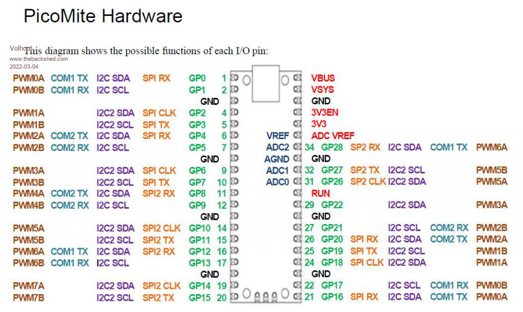 According to the PicoMite user manual, GP22 is PWM3A. I think you looked at PIN22. PIN22 is not GP22. I think T_out must be connected to GP16 (SPI_RX or also called MISO pin) to be able to read the coordinates from the Touch controller chip over the system SPI bus. Volhout Edited 2022-03-04 01:45 by Volhout PicomiteVGA PETSCII ROBOTS |
||||
| Mixtel90 Guru Joined: 05/10/2019 Location: United KingdomPosts: 8911 |
OPTION SYSTEM SPI GP18, GP19, GP16 'clk, mosi, miso OPTION LCDPANEL ILI9341, L, GP21, GP20, GP17, GP22 'or, dc, rst, cs, bl OPTION TOUCH GP15, GP14 'cs, irq I think the above should work fine, lew. GP22 is PWM3A so I don't think PWM3B can be used for PWM. You do need T_OUT if you are going to use touch. The backlight control was added later and isn't really in the best place in the manual IMHO. It would have needed rather a lot of messing about to put it elsewhere though, I think, as it only applies to a limited number of displays. EDIT: Volhout got in before me. :) Edited 2022-03-04 02:02 by Mixtel90 Mick Zilog Inside! nascom.info for Nascom & Gemini Preliminary MMBasic docs & my PCB designs |
||||
| phil99 Guru Joined: 11/02/2018 Location: AustraliaPosts: 3291 |
"So I not need T_out connected on the ILI9341?" T_out must go to GP16 along with SDO as noted by Volhout. |
||||
| lew247 Guru Joined: 23/12/2015 Location: United KingdomPosts: 1709 |
Thanks everyone |
||||
| Mixtel90 Guru Joined: 05/10/2019 Location: United KingdomPosts: 8911 |
The SPI is a bus, lew. The way it's used on the 'mites is that all devices on the bus have connections to clock, data into the master and data out from the master (note that the names change depending on the device). That would normally mean that all the devices conflict, but each device also has its own select line (CS) so that only one device is selected at once. The ILI9341 has 2 devices (3 if you use the SDcard), each with it's own CS line. So: These are the common bus lines PicoMite Display Touch SDcard SDI_TX (GP19) MOSI T_DIN SD_MOSI SDI_RX (GP20) MISO T_DOUT SD_MISO SDI_CLK (GP18) SCK T_CLK SD_SCK Then each device has its own select line PicoMite Display Touch SDcard GP17 CS - - GP15 - T_CS optional - - SD_CS There are also additional signals for the display and touch devices Sorry if I seem t be preaching to the converted, but you seem to be following the manual without an understanding of what is actually happening - which can be useful to know. Edited 2022-03-04 20:09 by Mixtel90 Mick Zilog Inside! nascom.info for Nascom & Gemini Preliminary MMBasic docs & my PCB designs |
||||
| The Back Shed's forum code is written, and hosted, in Australia. | © JAQ Software 2026 |
