
|
|
Forum Index : Microcontroller and PC projects : Help building a Colour Maximite 2 from a kit.
| Page 1 of 2 |
|||||
| Author | Message | ||||
| Mathew Newbie Joined: 10/12/2021 Location: United StatesPosts: 11 |
I was given a kit to build a Colour Maximite 2 and been having fun, but I seen to be stuck. It is a v3 motherboard by Geoff Graham and Peter Mather, which uses resistor arrays. The kit came with 220 ohm arrays instead of 240 ohm ones, so I ordered some 240 ohm ones from eBay. I am an experienced solderer, so I think I soldered everything correctly. Here are some pictures. It's in this state right now except I also populated the 14 point in socket in the top left.  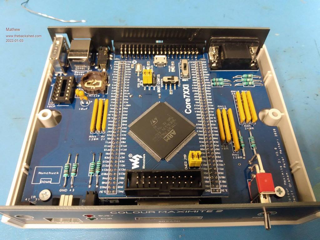 I uploaded the 5.07 firmware I found online (with jumpers removed like the instruction said), put the jumpers back on, plugged the power and monitor in and turned it on. The power light comes on, but there is no output to the monitor. Help would be appreciated. |
||||
| matherp Guru Joined: 11/12/2012 Location: United KingdomPosts: 10233 |
You need a battery fitted and all the jumpers removed from the waveshare module. Alternatively, no battery and just the VBAT jumper. |
||||
| Mathew Newbie Joined: 10/12/2021 Location: United StatesPosts: 11 |
For programming or running? Also, what are the proper switch settings on the waveshare for running? Looking at the waveshare, I notice what looks like a short between two legs of the main chip. This has me worried. 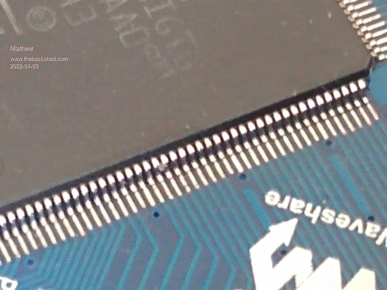 |
||||
| Mixtel90 Guru Joined: 05/10/2019 Location: United KingdomPosts: 7858 |
Will that bit of something shift with the aid of a pin or something? From your photo it doesn't look like solder. Mick Zilog Inside! nascom.info for Nascom & Gemini Preliminary MMBasic docs & my PCB designs |
||||
| matherp Guru Joined: 11/12/2012 Location: United KingdomPosts: 10233 |
For running Boot Switch to flash power switch to 5Vin all jumpers removed except VBat if no battery fitted. This is all in the constructors pack on Geoff's site |
||||
| Mathew Newbie Joined: 10/12/2021 Location: United StatesPosts: 11 |
The site has been down a while now. https://www.geoffg.net/Downloads/Maximite/CMM2_Construction_Pack.zip |
||||
| matherp Guru Joined: 11/12/2012 Location: United KingdomPosts: 10233 |
Works perfectly for me |
||||
| Frank N. Furter Guru Joined: 28/05/2012 Location: GermanyPosts: 947 |
...stupid question: Am I the only one who misses the oscillator??? 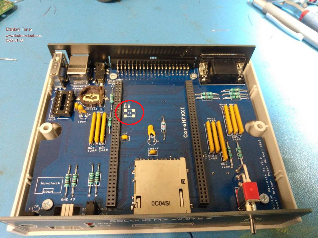 From "CMM2_G1_Construction Guide.pdf": External Oscillator The latest PCB has provision for an external 8 MHz crystal oscillator to replace the 8 MHz crystal on the Waveshare CPU board. This may be needed in some rare cases where a monitor has difficulty with some VGA modes (such as 800x600 pixel 16-bit colour). Most people will not need this modification however, if it is required, it can be implemented by installing the external oscillator and a capacitor on the motherboard (under the Waveshare CPU board). The 8MHz crystal on the Waveshare board does not have to be removed. The parts required are: 1 SMD 1206 100nF ceramic capacitor 1 8MHz oscillator in 5.0 x 7.0 mm SMD package (QX7 XO 25ppm). Eg, RS Stock Nbr 813-6194. Frank |
||||
| Mathew Newbie Joined: 10/12/2021 Location: United StatesPosts: 11 |
For me to now. It wasn't working all week for me, and even this morning! I'll take it. |
||||
| Mixtel90 Guru Joined: 05/10/2019 Location: United KingdomPosts: 7858 |
I've had problems with Geoff's site with *some* browsers. Others have no problems. It's always worth trying a different browser if you are having problems with a site. Pale Moon doesn't work for me (although I'm sure it did at one time). Vivaldi always does. Yes, I use the oscillator mod. I couldn't get some of the modes to work until I fitted it. The problem only seem to be with some Waveshare modules, I was one of the unlucky ones. Mick Zilog Inside! nascom.info for Nascom & Gemini Preliminary MMBasic docs & my PCB designs |
||||
| Mathew Newbie Joined: 10/12/2021 Location: United StatesPosts: 11 |
So since nothing else works should I try the external 8mhz crystal? Only place I can find one is 3 weeks shipping from China to the US on eBay Any suggestions on a better source? |
||||
| Mixtel90 Guru Joined: 05/10/2019 Location: United KingdomPosts: 7858 |
You should get something working without the crystal mod. The default screen mode should be fine even if you need the crystal mod later. Did you manage to get that bit of "something" out from between the pins of the chip? Mick Zilog Inside! nascom.info for Nascom & Gemini Preliminary MMBasic docs & my PCB designs |
||||
| Mathew Newbie Joined: 10/12/2021 Location: United StatesPosts: 11 |
The chip is clean and every test I do says it's fine but when I plug it in there's no display on the monitor. |
||||
| Mixtel90 Guru Joined: 05/10/2019 Location: United KingdomPosts: 7858 |
I rather hesitate to bring this up, but do the resistor networks you got have identical pinout to the 220R ones supplied? There are variations between packs. First, check your 5V supply on-load *at the CMM2*. Don't assume that your 5V supply lead is good until it's proved to be good. Many of them are made using damp spaghetti instead of copper. You need 5V. Did you successfully load the firmware onto the board? (manual Appendix G) Have you tried connecting to it via the serial console over USB to see if it's running? Edited 2022-01-07 23:51 by Mixtel90 Mick Zilog Inside! nascom.info for Nascom & Gemini Preliminary MMBasic docs & my PCB designs |
||||
| matherp Guru Joined: 11/12/2012 Location: United KingdomPosts: 10233 |
This is the most important thing. If you can connect over the serial console then the firmware is running. First thing you should see is the banner and a requirement to enter the keyboard type and time and date. As Mick says, you did get the correct resistor packs? They are not the ones with a common at one end but just individual resistors with each consecutive pair of pins connected to one resistor |
||||
TassyJim Guru Joined: 07/08/2011 Location: AustraliaPosts: 6269 |
220 ohms will be close enough if you find the 240 ohm ones are not the correct configuration. If you don't have a battery, you must have the VBAT jumper on.(all others off) Ignore the 8mhz xal mod for now. It is worth doing but it will not be the problem. Get the USB console working first. Then you can tackle the display. Jim VK7JH MMedit |
||||
bigmik Guru Joined: 20/06/2011 Location: AustraliaPosts: 2949 |
Hi Mathew, I haven't any personal experience with the waveshare version as I only have built the single board 1.5version all SMD. My experience is the battery needs to be fitted to get it to power up. I am concerned about the solder short on the wave share, you need to remove that, use solder wick and a hot iron but do not over heat the joints, if not moving, which it should. You could revert to a sharp scalpel but solder wick works well especially with some added flux. Another thing to be aware of is there are two types of resistor packs.. A type which have all resistors commoned to one pin (marked with a dot) and B type which are individual resistors. Always have even number of pins. If you replaced any resistor packs ensure you used the correct ones. Looking at the schematic they should be B type (at least for 240R ones) as there is no common point for the 240R resistors. The oscillator mod is only needed if you experience tearing or instability of the video output. Kind Regards, Mick Mick's uMite Stuff can be found >>> HERE (Kindly hosted by Dontronics) <<< |
||||
| Volhout Guru Joined: 05/03/2018 Location: NetherlandsPosts: 5056 |
Hi Mathew, Are you using the correct USB connector ? You use a USB A-A cable to program the firmware, using STcube PC software. But after that you use the USB-A port on the CMM2 for the keyboard. The USB-B connector connects to the PC if you use it for the PC editor. So you need 2 USB cables, and A-A and an A-B (if you want to connect a PC). If you use the CMM2 stand alone the USB-B to the PC is not needed. But mentioned here before, you can use the USB-B cable, and connect to a PC running W10 and the TeraTerm program (the PC will power the CMM2). If you open the correct serial port at 38400 baud in teraterm, you can communicate with the CMM2. Type <enter> and you will see a prompt, and can type basic commands. If that works, you know the CMM2 core works, and only the video output is the problem. If that does not work, the CMM2 core does not work and you have to check voltages(the basics). The crystal oscillator is only needed to stabilize the video output on the high resolution modes. As indicated this is not needed for all waveshare boards, and not for all monitors. But the crystal oscillator is not needed for the USB port experiment described above. Regards, Volhout PicomiteVGA PETSCII ROBOTS |
||||
| Mathew Newbie Joined: 10/12/2021 Location: United StatesPosts: 11 |
I just noticed I have a Core7XXI, but the BOM calls for a CoreH7XXI. Could that be the reason it's not working? Edit: I just pulled up the specs of the boards and they are very different. The non H core is 216mhz, and 1mb flash. The H core is 480mhz and 2mb flash, for instance! Edited 2022-01-13 09:23 by Mathew |
||||
| JohnS Guru Joined: 18/11/2011 Location: United KingdomPosts: 4038 |
Oh! That'll be the issue, I expect. John Edited 2022-01-13 10:02 by JohnS |
||||
| Page 1 of 2 |
|||||
| The Back Shed's forum code is written, and hosted, in Australia. | © JAQ Software 2025 |
