
|
|
Forum Index : Microcontroller and PC projects : General purpose I2C IO module
| Author | Message | ||||
| Turbo46 Guru Joined: 24/12/2017 Location: AustraliaPosts: 1590 |
No, not at all with the protocol Just the checksum, my SCADA background would always have me use a CRC. A checksum is just not secure enough (for me). You say that you have never had a checksum error so I presume that you have an ACK/NAK response from the slave if it detects a checksum error or not? On receipt of a NAK the master would re-send the message and count the number of re-tries? A checksum will not catch as many errors as a CRC, it's possible that you could have had errors without knowing it. @Mixtel90, regarding the DE signal, it's easy enough to generate your own and not use the one provided and invert it but that will rob you of an I/O pin of course. I think your automatic DE circuit is a copy of those used in commercial boards. I always thought a weakness of those is that the transmit signal has more propagation delay than the DE signal and it would be better to use the 'spare' gates in the receive signal path to further delay the transmit signal. Alternately, one trick I use to use was to insert a (say) 1meg resistor in series with an input, which forms an RC network with the gate's input capacitance and will cause a delay in the signal. Just thinking that the first bit in the transmit may be truncated, not by much I admit. Rather than use the DB9 connector for the RS485 signal I would use the more conventional screw terminals (and no 5v). That means you have to take the lid from the box to connect it but... I like it. It could be used to make a MODBUS slave. Hmmm. Bill Keep safe. Live long and prosper. |
||||
| Mixtel90 Guru Joined: 05/10/2019 Location: United KingdomPosts: 5705 |
I doubt if the Micromite is up to easily handling MODBUS and CRC stuff. Not unless you write some CSUBs to sort it out anyway. There are only 17 IO pins available once you've taken two away for comms. I didn't want to lose one for DE (although it would have been easy), hence the automatic DE. My design is to fit a specific box. I don't like the DB9 really because it's bulky, but it works and it's secure. Screw terminals invites messing with a box that might be live. Not good really. Mick Zilog Inside! nascom.info for Nascom & Gemini Preliminary MMBasic docs & my PCB designs |
||||
| Turbo46 Guru Joined: 24/12/2017 Location: AustraliaPosts: 1590 |
I've done it. Four DI, four DO and two analogue inputs. Response time is under 10mS if I remember correctly. I want to change the way that the baud rate, slave address and DO operate time is set up. My next job after I finish my current project (maybe). Bill Edit: I understand your view on the DB9 but it's not for me. Someone who builds one should be well aware of what's inside. Edited 2022-01-10 11:05 by Turbo46 Keep safe. Live long and prosper. |
||||
| Volhout Guru Joined: 05/03/2018 Location: NetherlandsPosts: 3496 |
Just to be involved in the discussion: I like the board, think it is a nice addition. The discussion about DB9 / screw terminals is more a discussion about what the board is used for. If this is a (remote) expansion unit for a PC, the DB9 is fine. If it is one of multiple modules (how do you set the Modbus address ?) in a system DB9 is not easy to assemble. Each connector needs 2 wires in one pin, and 2 cables through the strain relief. Then screw terminals would be much easier. If you would add optical isolation you could avoid ground loops, but depending on how you engineer the digital IO and especially the 2 analog channels, that may not be needed. The timing of your DE generation circuit must be "tuned" to the envisioned baudrate, otherwise you end up with missing data with a low /silent time/dead time/turn around time/ modbus master. I would always use the DE pin of the MX170 to avoid that. Rather loose 1 pin on the micro than having to debug this kind of problems in a system that works 99% of the time. And this is recent.. I've done it Mixtels way, the customer ran the modbus test suite and came back with the exact error with low turn around time masters, and I had to change the design. Regards, Volhout Edited 2022-01-10 17:55 by Volhout PicomiteVGA PETSCII ROBOTS |
||||
| JohnS Guru Joined: 18/11/2011 Location: United KingdomPosts: 3649 |
Just wondering... why CSUBs? CRC is OK, especially if done as each byte comes in. John |
||||
| Turbo46 Guru Joined: 24/12/2017 Location: AustraliaPosts: 1590 |
Good point about multiple modules. The DB9 connector would be a nightmare. Set the address and baudrate by sending values to a register. Say the initial address is 1, the baudrate is 1200, change them to whatever you need with a setup message. Any isolation for I/O or communications should be up to those who wish to use it. Requirements will vary. The automatic DE circuit could be specified for a range of baudrates - although I prefer using one generated by software and not using the inbuilt inverted one. MODBUS messages are fairly short and using the table lookup method for CRC generation or checking is relatively fast. I process the whole message in one go. Bill Keep safe. Live long and prosper. |
||||
| Mixtel90 Guru Joined: 05/10/2019 Location: United KingdomPosts: 5705 |
Here's a 16 IO version using hardware DE and pluggable terminals. There's space for a data loopthrough now, but not for the 5V. Of course, you aren't supposed to do multidrop usung loopthrough terminals as unplugging one node kills everything after it. :) These terminals make it easy to connect/disconnect as the actual terminal is outside the box. Note that the pins are 1mm sq and on 5mm centres so fixed terminals might also fit the board. I don't like not having 5V on the same connector, but my usual supplier doesn't stock 4-pin horizontal sockets. It would work well with 2-pair cable with no screen needed. 3-pin really needs single-pair screened and you still need to provide external power. I'm not bothered about the firmware for MODBUS - I won't be writing it. :) I have had a bit of a read up on CRC generation and checking though and it looks a right pain in the backside, even if you've finally decided on which of the 500 incompatible versions you prefer. One of those things that was originally designed to be done in hardware, not software. The MODBUS address has to be set in firmware and written in sharpie on the box. :) Use a CONST THIS_IS_MY_MODBUS_ADDRESS_AT_THE_MOMENT = n at the beginning to make it easy to change. EDIT: OOPS! DE should either be inverted (add a transistor) or have a pull-down resistor if it's being handled in software. 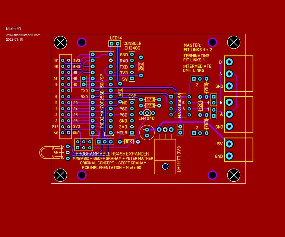 Edited 2022-01-10 18:41 by Mixtel90 Mick Zilog Inside! nascom.info for Nascom & Gemini Preliminary MMBasic docs & my PCB designs |
||||
| Turbo46 Guru Joined: 24/12/2017 Location: AustraliaPosts: 1590 |
@Mixtel90  Not entirely sure but I think you are using the DE pin for DE while this is inverted I think that is not a problem because it it is not specified in the comspec then it can be toggled in the software. I'm happy to have one A/B/E connector because a slave in the middle of a daisy chain can be removed without breaking the circuit for those further on. I expect that depends on how you connect them up. Bill Keep safe. Live long and prosper. |
||||
| Tinine Guru Joined: 30/03/2016 Location: United KingdomPosts: 1646 |
@Turbo46 A "Status Byte" (+checksum) is always returned and one of the 8 bits is a flag to alert of a checksum error. There are no retries, errors are simply not tolerated. It's a command/response arrangement and so no chance for collisions. |
||||
| Tinine Guru Joined: 30/03/2016 Location: United KingdomPosts: 1646 |
Modbus...fruit of the shed? |
||||
| Tinine Guru Joined: 30/03/2016 Location: United KingdomPosts: 1646 |
DB9 - they are available with BOBs Screw terminals are soooo 2010. Today we use screwless  |
||||
| Turbo46 Guru Joined: 24/12/2017 Location: AustraliaPosts: 1590 |
Yes, that's mine I'm a little intrigued by "no retries". Does that mean that it is not important if a command does not get through? Bill Keep safe. Live long and prosper. |
||||
| Tinine Guru Joined: 30/03/2016 Location: United KingdomPosts: 1646 |
Nice work  Fruit of the shed doesn't get enough love Fruit of the shed doesn't get enough love My nodes are distributed servo controllers for machine tools. 16 axes (nodes) can be tightly coordinated (on a serial network!!!) but there is no time for retries as each PID is processed in 512uS. Furthermore, an error can only mean an electrical fault which needs to be remedied. Similarly, each servo-motor is fitted with an incremental encoder that generates pulses (5v) and feeds them to the controller chip via line-drivers/receivers. This is how the controller handles position and velocity (dp/dt) of each axis. In my case, these are hundreds of KHz. Here, there is no verification of signal integrity at all. The pulses are simply counted. A loss of pulses can result in a destroyed machine. |
||||
| Turbo46 Guru Joined: 24/12/2017 Location: AustraliaPosts: 1590 |
Sounds impressive. I have no experience of anything like that. Bill Keep safe. Live long and prosper. |
||||
| Mixtel90 Guru Joined: 05/10/2019 Location: United KingdomPosts: 5705 |
I've done another pcb move round of the RS485 version. Terminals are a 2-pole for 5V & GND and 3-pole for A, B & GND. It should be possible to fit either fixed or pluggable terminals. Looping through the pluggable terminals would allow disconnection without breaking the chain. Alternatively a lead to a DB9 plug could plug into a loop-connected terminal box & power supply. I've also rearranged the terminating resistor links so they are accessible externally if required or can be kept internal. I've had a thought on the MODBUS address and come up with this: Initially all devices have the same address. To commission, connect a single unit and write a value (the address) to a dummy analogue port. The firmware should recognise this port and store the value in an address register. On power up it should compare the address register with the default value and, if it is different, use the register as the address. It could also be written so that the IO won't work when using the default address, so devices have to be commissioned before they can work. I'm not sure how you could reset a commissioned device to it's default address if you didn't know it's address. That would probably have to be done via the console. Mick Zilog Inside! nascom.info for Nascom & Gemini Preliminary MMBasic docs & my PCB designs |
||||
| Turbo46 Guru Joined: 24/12/2017 Location: AustraliaPosts: 1590 |
My method would be to: Set a default address in the firmware, say 1. Set a default baud rate in the firmware, whatever. To set the new address, send a command using function code 10 (set multiple registers) to set a 'register' to the required address. VAR SAVE it. Load the saved address on startup. Do the same for the baud rate. Could be done in the same message. Change it again if you want to. Reset the firmware if you muck it up. Bill Keep safe. Live long and prosper. |
||||
| Tinine Guru Joined: 30/03/2016 Location: United KingdomPosts: 1646 |
Realising that pins are precious, the following is probably of no interest but it's what I have. Dynamic address allocation: Master broadcasts address_1 1st slave: Addr_In pin is tied high and has no address Takes address_1 and sets its Addr_Out pin high which feeds Addr_In of 2nd slave Master broadcasts address_2 1st slave already has an address but 2nd slave doesn't and its Addr_In pin is high 2nd slave takes address_2 and sets its Addr_Out pin high which feeds Addr_In of 3rd slave....and so-on. Yes it costs 2 pins and requires an extra "address" wire.  |
||||
| Mixtel90 Guru Joined: 05/10/2019 Location: United KingdomPosts: 5705 |
I keep wondering if MODBUS isn't rather a lot of overkill for these. :) Surely something like the system used for the I2C version might be more in line with something so simple? Ok, you could add a checksum or something, but MODBUS feels like using a sledgehammer to crack a nut. RS485 gives the extra range, but the protocol could be anything. Edited 2022-01-11 08:07 by Mixtel90 Mick Zilog Inside! nascom.info for Nascom & Gemini Preliminary MMBasic docs & my PCB designs |
||||
| Tinine Guru Joined: 30/03/2016 Location: United KingdomPosts: 1646 |
Overkill and overhead. Too darned clunky for me. |
||||
| Turbo46 Guru Joined: 24/12/2017 Location: AustraliaPosts: 1590 |
I completely agree. I2C as per the original concept is the way to go for a module adjacent to the Master. A MODBUS slave is just something I want to do. It is relatively simple to just implement the parts of it that you need. Yes, RS485 gives the extra range and yes, the protocol could be anything. But a CRC is dead easy to use once the routine is in the firmware. Thank you for the board designs. Bill Keep safe. Live long and prosper. |
||||
