
|
|
Forum Index : Microcontroller and PC projects : Alternative take on the 5" SSD1963 + PicoMite
| Page 1 of 2 |
|||||
| Author | Message | ||||
| Mixtel90 Guru Joined: 05/10/2019 Location: United KingdomPosts: 5705 |
I couldn't resist when Peter asked Grogster for an adapter board... I omitted the 7" option as I have no mechanical info on that, or any requirement for one. However, I did attempt to make up for the lost IO using a Micromite. 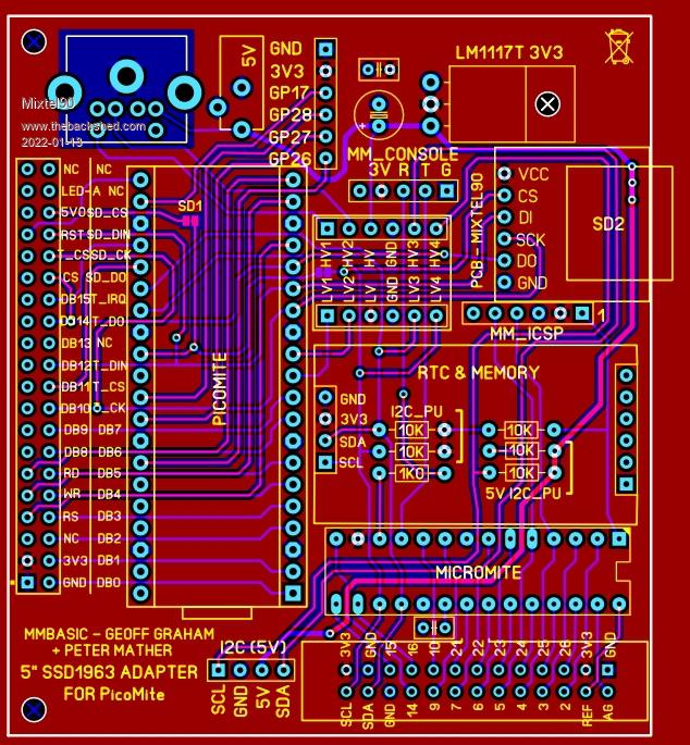 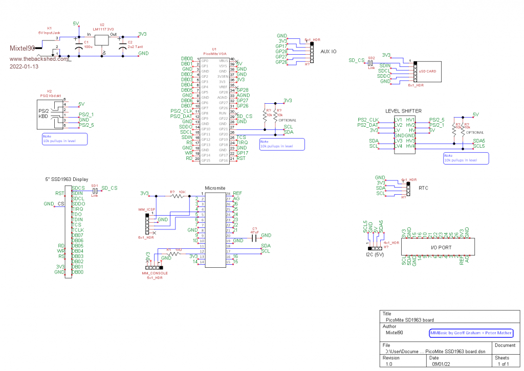 Mick Zilog Inside! nascom.info for Nascom & Gemini Preliminary MMBasic docs & my PCB designs |
||||
| lizby Guru Joined: 17/05/2016 Location: United StatesPosts: 3008 |
Now you're talking. Did someone say, "On a roll". I think Grogster's 9" EastRising SSD1963 adaptor would work on this (but I haven't looked closely). Now we need breakouts for the MX150 pinout. Again functional similarity to the F4, but maybe fewer solder points. PicoMite, Armmite F4, SensorKits, MMBasic Hardware, Games, etc. on fruitoftheshed |
||||
| Mixtel90 Guru Joined: 05/10/2019 Location: United KingdomPosts: 5705 |
Oh, the 5V I2C interface on this should interface directly with the I2C expander (same connector, same pin order). The blob connectors for the SD cards are normally both enabled, but you can cut one or the other to disable it if required. I've tried doing a version for RS485 instead of I2C but it's not working out well. The MAX485 is a 5V chip so I have to use two of the level shifters for it and the track weaving is a pain. I'd like to stick with the same chip really. It might still happen. :) Can you still get the MX150? (Come to think of it, can you still reliably get *any* silicon?) Mick Zilog Inside! nascom.info for Nascom & Gemini Preliminary MMBasic docs & my PCB designs |
||||
| lizby Guru Joined: 17/05/2016 Location: United StatesPosts: 3008 |
Sorry, meant MX170, "MM2" micromite. Re "breakout", I meant routing the output pins of the micromite header to a user-specific configuration--a custom PCB (which the user would have to design). PicoMite, Armmite F4, SensorKits, MMBasic Hardware, Games, etc. on fruitoftheshed |
||||
| Mixtel90 Guru Joined: 05/10/2019 Location: United KingdomPosts: 5705 |
Well, you can use the RPi "breakout" cable. No point in routing the CMM2 to line up with a parallel (or SPI for that matter) LCD display as it doesn't support them. Did you have something particular in mind? Mick Zilog Inside! nascom.info for Nascom & Gemini Preliminary MMBasic docs & my PCB designs |
||||
| lizby Guru Joined: 17/05/2016 Location: United StatesPosts: 3008 |
"MM2" (MX170), not "CMM2". Which RPi "breakout" cable for the 2x13 header? >Did you have something particular in mind? Just a variation of PaulL's geothermal controller: 2 on/off, 2 count, 13 temp inputs, 7 outputs, SSD1963 GUI, e.g., for the Explore-64: SSD1963 D5 1 | + + | 64 SSD1963 D4 SSD1963 D6 2 | + + | 63 SSD1963 D3 SSD1963 D7 3 | + + | 62 SSD1963 D2 spi2 clk (SD, LCD) 4 | * + | 61 SSD1963 D1 spi2 out (SD, LCD) 5 | * + | 60 SSD1963 D0 CONSOLE RX 6 | | 59 COM1: RX ESP-01 *Reset 7 | | 58 CONSOLE TX SPI1 out 8 | MM64 + | 55 output5 COM2: TX 11 | Explore + | 54 output6 SD Card Chip Select 12 | * PCB | 53 output7 COM2: RX 13 | + | 52 Water Volume to Yard SD Card Detect 14 | * + | 51 Water Volume to Tank ESP-01 COM1: TX 15 | + | 50 Yard Feed Temp output1 COM3: TX 16 | sim + | 49 input15 ?Blower output2 COM3: RX 17 | sim + | 48 input14 Deep Ground Temp Freon Low Temp 18 | + * | 47 spi2 in (SD, LCD) Freon Exp. Low Temp 21 | + + | 46 Yard Return Temp Freon Exp. High Temp 22 | + | 45 output4 Tank Feed Temp 23 | + * | 44 I2C Clock Tank Return Temp 24 | + * | 43 I2C Data (RTC) Tank Center Temp 27 | + | 42 Freon High Temp TCP ESP-01 reset 28 | | Hallway Temp 29 | + | Outside Temp 30 | + | 3.3V output (100mA max) output3 31 | | 5V (input or output) Generator ON/OFF 32 | + | 0V Mains ON/OFF 33 | + | ~ Edited 2022-01-14 05:25 by lizby PicoMite, Armmite F4, SensorKits, MMBasic Hardware, Games, etc. on fruitoftheshed |
||||
| Mixtel90 Guru Joined: 05/10/2019 Location: United KingdomPosts: 5705 |
Oh, sorry. I'm not conversant with the MM2 or the MM64 Explore. I've seen them mentioned, that's all. :) The CMM2 can use a RPi 40-pin GPIO cable to connect it to a breadboard. You can connect whatever you like then. The 2x13 header used to be used for RS-232 connections from a DB25 connector to a board. Very easy to get the bits and make your own cables if you have a bench vice (although I've been known to use a block of wood and a hammer before now. lol (puts salesman hat on) You should be able to implement that geothermal controller with a SSD1963 display, a PicoMite, this SSD1963-PicoMite adapter board and this I2C expander module, sir. :) Mick Zilog Inside! nascom.info for Nascom & Gemini Preliminary MMBasic docs & my PCB designs |
||||
| lizby Guru Joined: 17/05/2016 Location: United StatesPosts: 3008 |
"MM2" ("Micromite II") is what's on your board, 28-pin MX170 chip. (I think Micromite I was the MX150 version, but I'm not sure because that was before my time on the forum.) I'll order the board to have a play when you post the gerbers. A play is all it will be, since the project never made it to implementation. With 3300+ lines of code, though, and a lot of I/O it does provide a pretty good MMBasic workout. PicoMite, Armmite F4, SensorKits, MMBasic Hardware, Games, etc. on fruitoftheshed |
||||
| Mixtel90 Guru Joined: 05/10/2019 Location: United KingdomPosts: 5705 |
Sheesh... it sounds like it was quite a feat! :) I think you're right about the MX150. Geoff mentions it in the Micromite manual, pointing out that the current code no longer runs on it. The only thing that bothers me about the board as it stands is that I'm not sure how much space there is under that RTC module because the battery seems to be there. As you can see, I've put resistors underneath so I'm hoping there's enough space! I've not got one to measure and, of course, there's no mention of that dimension in adverts. I suppose the resistors could go on the bottom of the board if it turns out not to fit. Mick Zilog Inside! nascom.info for Nascom & Gemini Preliminary MMBasic docs & my PCB designs |
||||
| lizby Guru Joined: 17/05/2016 Location: United StatesPosts: 3008 |
My own preference for an RTC module is this one PicoMite, Armmite F4, SensorKits, MMBasic Hardware, Games, etc. on fruitoftheshed |
||||
| Mixtel90 Guru Joined: 05/10/2019 Location: United KingdomPosts: 5705 |
I like that one, but I've had a couple that aren't terribly accurate. In fact, on the RS485 version of this board that I've been playing with, I used one of these to gain more board space. It's also what I used on my PicoMite Backpack and what I've built into the I2C expansion module. Edited 2022-01-14 07:47 by Mixtel90 Mick Zilog Inside! nascom.info for Nascom & Gemini Preliminary MMBasic docs & my PCB designs |
||||
| lizby Guru Joined: 17/05/2016 Location: United StatesPosts: 3008 |
Here are 2x13 flat ribbon cable and IDC26 sockets. How many PicoMite pins are available? ~ Edited 2022-01-14 09:28 by lizby PicoMite, Armmite F4, SensorKits, MMBasic Hardware, Games, etc. on fruitoftheshed |
||||
| lizby Guru Joined: 17/05/2016 Location: United StatesPosts: 3008 |
Hmmm, by my count, with 24 pins needed (2 count, 2 on/off inputs, 12 temperature, 8 output) and with no keyboard, GP8,9,17,26,27,28 available on the Picomite, I'm one pin shy unless pins 11 & 12, console Tx and Rx, are available for use. And I'd like to have 2 pins available for an ESP-01. Picomite: GP08 Yard & Tank Pump GP09 Hot water Boiler Gas & Pump GP17 Air Handler Pump & Blower GP26 Air Handler Burner GP27 Freon Compressor GP28 Freon Reverse and *Reset 1 | | 28 ANALOG POWER Mains ON/OFF 2 | | 27 ANALOG GROUND Tank Feed Temp 3 | | 26 Blower Tank Return Temp 4 | | 25 Freon Low Temp Tank Center Temp 5 | | 24 Freon Exp. Low Temp Outside Temp 6 | MM28 | 23 Freon Exp. High Temp Generator ON/OFF 7 | I/O | 22 Yard Feed Temp 0V 8 | | 21 Yard Return Temp Hallway Temp 9 | | 20 +V TANT CAP Deep Ground Temp 10 | | 19 0V CONSOLE TX 11 | | 18 I2C Data (Picomite, RTC) CONSOLE RX 12 | | 17 I2C Clock VCC 2.3-3.6V 13 | | 16 Water Volume to Yard Freon High Temp 14 | | 15 Water Volume to Tank Pin lacking for Joist Pump (but since this is just for playing, that auxiliary pump can be omitted). The code for the MX170 in the Getting Started with the Micromite manual doesn't include reading a temperature from a DS18B20, so that code would have to be added--not hard to do with a little fiddling to make sure that the temperature that is returned instantaneously has been read in the past second. Considering the shortage of pins on the Picomite, I wonder if 8-bit parallel might be considered for the SSD1963 as with the MM+ (see page 13 in the MM+ Manual) instead of 16-bit parallel. PicoMite, Armmite F4, SensorKits, MMBasic Hardware, Games, etc. on fruitoftheshed |
||||
| Mixtel90 Guru Joined: 05/10/2019 Location: United KingdomPosts: 5705 |
Using the SSD1963 (in 8-bit mode) a USB keyboard and SD card on the PicoMite there are 6 spare pins. I used two of those for I2C to give me a further 17 from the Micromite, so that's 21 IO in total. I don't consider the Micromite IO to be particularly slow for control purposes - the real world is usually a lot slower than I2C. :) Of the 4 remaining pins 3 are the PicoMite ADC inputs and the Micromite has a further 10, so there are 13 possible analogue inputs, if you felt like going that way. A PicoMite is now cheaper than an "official" 28-pin MX170 bought from Farnell. The main reason I didn't use one for the I2C expansion module is it's lack of ADC inputs. Mick Zilog Inside! nascom.info for Nascom & Gemini Preliminary MMBasic docs & my PCB designs |
||||
| lizby Guru Joined: 17/05/2016 Location: United StatesPosts: 3008 |
Ahh, d'oh--seeing DB08-DB15 labelled on the PCB I didn't twig that they were unconnected, so the SSD1963 is already in 8-bit mode. I also didn't realize that the I2C slave could be another picomite--that might be a better solution for me, since space isn't all that tight. PicoMite, Armmite F4, SensorKits, MMBasic Hardware, Games, etc. on fruitoftheshed |
||||
| Mixtel90 Guru Joined: 05/10/2019 Location: United KingdomPosts: 5705 |
I think I've solved having an I2C connected Micromite (still with SDA and SCL on the IO connector, but 3V3 only, I'm afraid) and a 5V RS485 connection both on the SSD1963 adapter board. :) Down to just GP26 free now. Should I add a buzzer? Hmmm... You can run any of the 'mites as an I2C master or slave AFAIK, providing there is some sort of I2C port - even if it's bitbanged. The MMBasic code is in the Getting Started manual for the Micromite and it's very simple. (Nice one Geoff!) Mick Zilog Inside! nascom.info for Nascom & Gemini Preliminary MMBasic docs & my PCB designs |
||||
| lizby Guru Joined: 17/05/2016 Location: United StatesPosts: 3008 |
Hmm, I don't see I2C SLAVE as a command in the Picomite manual, and I get this: run [5] I2C SLAVE OPEN &H26, 0, 0, WriteD, ReadD ' slave's address is 26 (hex) Error : Syntax It's not in the MM+ or F4 manual either, so perhaps it's only on the MM2. Might be interesting to try the 44-pin MM2. I have a vague recollection of having had one at some point. PIC32MX170F256D-50I/PT (MM2-44) at Digikey: $8.13, 0 in stock, Manufacturer Standard Lead Time 52 Weeks. ~ Edited 2022-01-15 02:17 by lizby PicoMite, Armmite F4, SensorKits, MMBasic Hardware, Games, etc. on fruitoftheshed |
||||
| matherp Guru Joined: 11/12/2012 Location: United KingdomPosts: 8566 |
Missing in the command list but in Appendix B and see here. Syntax slightly different to MM2 |
||||
| Mixtel90 Guru Joined: 05/10/2019 Location: United KingdomPosts: 5705 |
The result of today's playtime: RS485 version. I had to lose the ICSP connector, but that's hardly a deal breaker as all the signals are on the IO connector. Only GP28 is left now. DE is under user control as the PicoMite doesn't appear to support an automatic mode. I2C at 3V3 is available on the IO connector. The odd arrangement of the RS485 connector allows for easy connection of two twisted pairs or a 4-core flat cable (only for short distances, I think, but might be useful). You can also do A+B+Gnd quite easily. I'm only thinking of a Dupont connector here as a controller should be in a box. 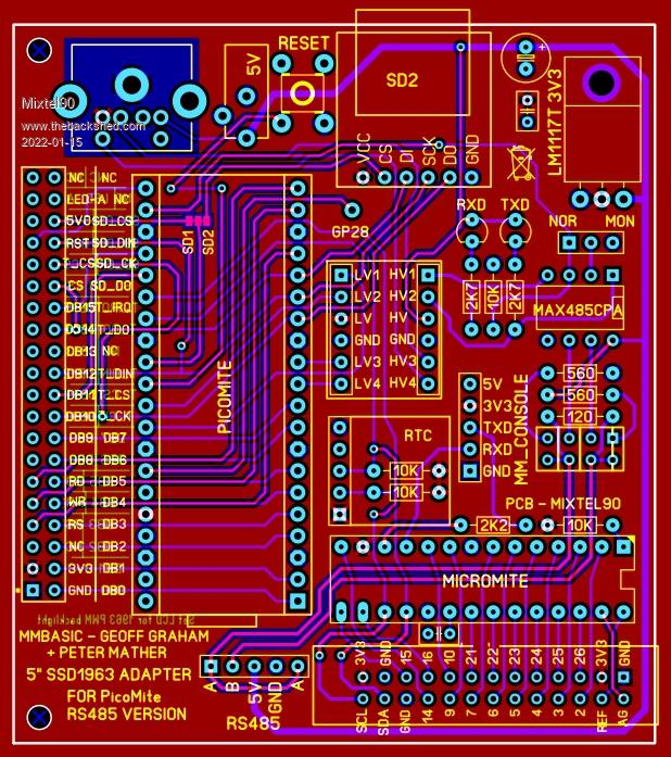 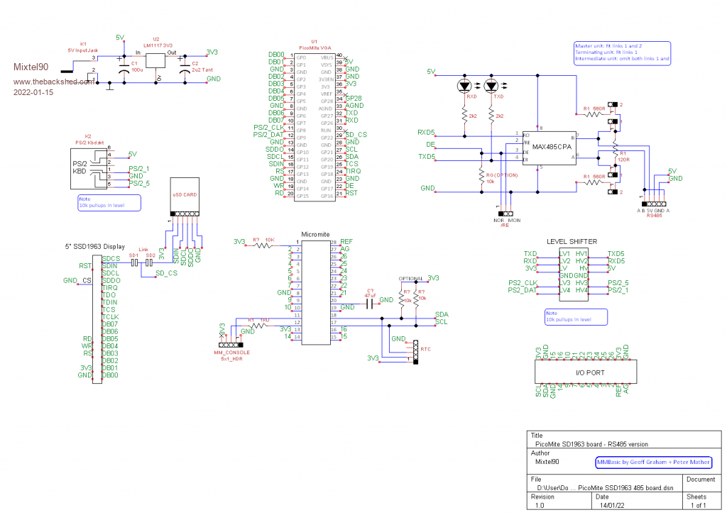 Mick Zilog Inside! nascom.info for Nascom & Gemini Preliminary MMBasic docs & my PCB designs |
||||
| flasherror Senior Member Joined: 07/01/2019 Location: United StatesPosts: 159 |
Nice PCB. A suggestion: move RS485 connector a little away from the micromite I/O connector, it looks kind of close. Also, it doesn't look like there are mounting holes on right side (unless the regulator PCB hole is intended to be a mounting hole?) Or maybe this is designed to fit a box? Might need mechanical support if plugging/unplugging things into micromite connector? I know you attach schematics, but can you upload .zip of them? Some of the text readability is not great considering large images are resized during upload. Also, what are the SD card and RTC modules? Edited 2022-01-15 10:31 by flasherror |
||||
| Page 1 of 2 |
|||||
