
|
|
Forum Index : Microcontroller and PC projects : Where are the pull-ups and decoupling caps on the full size SD readers
| Author | Message | ||||
| thwill Guru Joined: 16/09/2019 Location: United KingdomPosts: 4369 |
... attached to the cheap SPI LCDs such as the one used on the PicoMite backpack c.f. those on the little MicroSD reader modules ? Are they within the metal casing, or am I making sh*t up? Note I'm not talking about the troublesome inline resistors on those same LCD displays, I've bought some 0R SMDs to deal with those blighters. Best wishes, Tom MMBasic for Linux, Game*Mite, CMM2 Welcome Tape, Creaky old text adventures |
||||
| matherp Guru Joined: 11/12/2012 Location: United KingdomPosts: 11512 |
You don't need or really want pullups for SPI. You do need them for SDIO depending on the weak pullups available in a particular processor |
||||
| phil99 Guru Joined: 11/02/2018 Location: AustraliaPosts: 3290 |
"Note I'm not talking about the troublesome inline resistors on those same LCD displays, I've bought some 0R SMDs to deal with those blighters" Rather than replacing them I found it easier to solder a thin strand of wire across the top of them. Make it long enough to hold while soldering then snip the excess. You don't need to do the SD_CS one as it doesn't cause a problem. On my most recent panel I soldered thin enameled wire direct from the SD socket pads to the header pads, before installing the header. Much easier than dealing with SMD sizes. |
||||
| thwill Guru Joined: 16/09/2019 Location: United KingdomPosts: 4369 |
Thanks Phil, That's how I started out but with my modest skills I had no end of trouble, the solder on both ends of such a short piece of wire was becoming molten simultaneously so I could never get the bl**dy thing to "stick" and ended up lifting a pad that I then had to botch. I find SMD resistors much less slippery customers and the next size up works as replacements on those boards. Worth knowing, thank you. I might try that next time ... though probably with wirewrap wire; solderable enamelled wire is another one of my bugbears, I know I should be able to get it to "work" but 50/50 I end up with a black over-heated mess or the enamel stubbornly resistent to burning off. Best wishes, Tom MMBasic for Linux, Game*Mite, CMM2 Welcome Tape, Creaky old text adventures |
||||
| thwill Guru Joined: 16/09/2019 Location: United KingdomPosts: 4369 |
OK, thanks Peter, still trying to get my head around this since you said SD card adapters with resistors are bad and then recommend the one on the left for the VGA PicoMite. 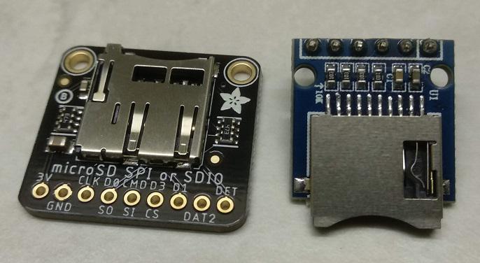 But I now (hopefully) understand that it's the inline resistors that you object to and those on these adapters are pull-ups. I'm correct in thinking that the capacitors on both these boards are the "decoupling capacitors" such as the 10uF and 0.1uF I might see on a breadboard an IC? Best wishes, Tom MMBasic for Linux, Game*Mite, CMM2 Welcome Tape, Creaky old text adventures |
||||
| matherp Guru Joined: 11/12/2012 Location: United KingdomPosts: 11512 |
The pullup resistors on the adafruit adapter are 47K. This is correct for SDIO and irrelevant for SPI. Many boards have much lower values which is just wrong in all cases |
||||
| phil99 Guru Joined: 11/02/2018 Location: AustraliaPosts: 3290 |
" or the enamel stubbornly resistent to burning off." For self fluxing ECW scrape some enamel off one side to give the solder some contact with the copper and it will flow under the enamel, which then flakes off. As you have found it can be much more difficult than the manufacturers claim, using heat alone. |
||||
| The Back Shed's forum code is written, and hosted, in Australia. | © JAQ Software 2026 |
