
|
|
Forum Index : Microcontroller and PC projects : My mind is blank
| Page 1 of 2 |
|||||
| Author | Message | ||||
lew247 Guru Joined: 23/12/2015 Location: United KingdomPosts: 1709 |
Can anyone tell me what I've done wrong? I'm trying to get the Picomite to display everything coming from the GPS unit but I get nothing when I run the program SETPIN rx, tx, COM1 and according to every pinout diagram I have then GPIO1 is RX and GPIO0 is TX I've even tried setpin GP0,GP1, Com1 but it still gives no output on the console setpin GP1,GP0, Com1 Open "COM1:115200" AS GPS,0,1 DO If GPS(VALID) = 1 Then print GPS(date) print GPS(time) END IF pause 1000 Loop I've tested the GPS module on the PC using a uart adaptor and it works perfectly and the baud rate is 115200 it receives all 4 different gps constellations and I can see the output from the GPS unit on the serial console on the PC and using the Ublox software as well. |
||||
| matherp Guru Joined: 11/12/2012 Location: United KingdomPosts: 11513 |
Are you connecting Rx to tx and visa versa? You should be. |
||||
| lew247 Guru Joined: 23/12/2015 Location: United KingdomPosts: 1709 |
Yes, exactly the same as I had it on the PC uart adaptor tx to rx and rx to tx TX on the GPS to GPI and RX on the GPS to GP0 |
||||
| thwill Guru Joined: 16/09/2019 Location: United KingdomPosts: 4369 |
I'm working the same project as Lewis and seeing exactly the same problem though I haven't gone through the process of eliminating all user error yet. This was all working before Christmas and I'm starting to wonder if there is any chance that GPS somehow got broken in the latest PicoMite builds ? (but even so I would have thought I could have got something from it by treating it as a non-GPS serial device) - I'm running the 5.07.03 release (what about you Lewis?), but I'm hoping I've got a PicoMite running the earlier *working* version somewhere. Currently haven't got any free time until Friday to investigate further though. Best wishes, Tom Edited 2022-02-02 23:55 by thwill MMBasic for Linux, Game*Mite, CMM2 Welcome Tape, Creaky old text adventures |
||||
| Volhout Guru Joined: 05/03/2018 Location: NetherlandsPosts: 5931 |
Hi Lew247, Do you have any conflicting options set (like OPTION SYSTEM SPI or OPTION I2C on these pins ?) Sorry, I ran out of picomites, so I can't help you with debugging... Regards, Volhout Edited 2022-02-03 00:18 by Volhout PicomiteVGA PETSCII ROBOTS |
||||
| lew247 Guru Joined: 23/12/2015 Location: United KingdomPosts: 1709 |
Apologies everyone I had indeed somehow got the tx and rx on the Pico reversed, even though I was positive I had it correct Rx the GPS goes to Pin 1 on the Pico and TX on the GPS to Pin 2 on the Pico Tom This code works setpin GP1,GP0, Com1 Open "COM1:460800" AS GPS,0,1 DO If GPS(VALID) = 1 Then print GPS(date) print GPS(time) END IF pause 1000 Loop ***change the baud rate to what you have yours set at - it will be much lower*** |
||||
| thwill Guru Joined: 16/09/2019 Location: United KingdomPosts: 4369 |
Great ... and I made the same mistake. Lewis assuming that the PicoMite manual is correct you've transposed RX and TX on all the schematics for the PicoMite GPS Speedometer ... no wonder we've been having difficulty  . .Best wishes, Tom Edited 2022-02-03 01:53 by thwill MMBasic for Linux, Game*Mite, CMM2 Welcome Tape, Creaky old text adventures |
||||
| Mixtel90 Guru Joined: 05/10/2019 Location: United KingdomPosts: 8911 |
My mind's been a blank for years. Just ask Mrs Mixtel90 ... :( Mick Zilog Inside! nascom.info for Nascom & Gemini Preliminary MMBasic docs & my PCB designs |
||||
| Plasmamac Guru Joined: 31/01/2019 Location: GermanyPosts: 620 |
I know that feeling.  Plasma |
||||
| lew247 Guru Joined: 23/12/2015 Location: United KingdomPosts: 1709 |
2nd question: How do I connect an ILI9341 to the Picomite? The standard Rp2040 board with 40 pins Where does the LED pin connect to? In the manual I see this: Does this mean the LED pin on the ILI9341 can be connected to GP11? or does it have to have it's own 3.3V or 5V power? |
||||
| Mixtel90 Guru Joined: 05/10/2019 Location: United KingdomPosts: 8911 |
On the more recent displays the LED pin is connected to the base of a transistor (Q1 on the display) via a 1k resistor. You can connect it direct to 3V3 to get full brightness or to a digital output for On/Off or PWM control. Early versions didn't have the transistor and an external one was needed. Mick Zilog Inside! nascom.info for Nascom & Gemini Preliminary MMBasic docs & my PCB designs |
||||
| lew247 Guru Joined: 23/12/2015 Location: United KingdomPosts: 1709 |
So I can't just connect an ILI9341 display directly to one of these? The manual says nothing about not being able to 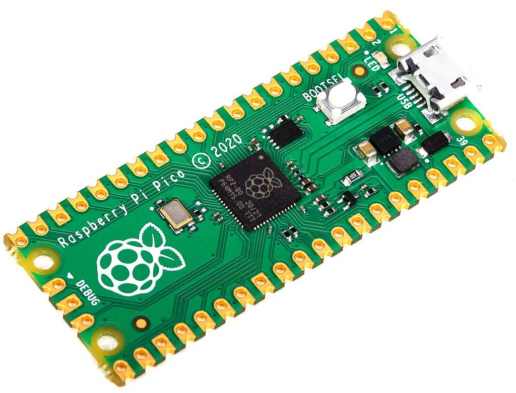 Edited 2022-02-03 05:04 by lew247 |
||||
| Mixtel90 Guru Joined: 05/10/2019 Location: United KingdomPosts: 8911 |
The PicoMite manual describes how to do it on page 43. :) OPTION LCDPANEL ILI9341, OR, DC, RESET, CS more detail on page 48 OPTION LCDPANEL ILI9341, OR, DC, RESET, CS, Backlight Exactly which pins you use is up to you - you set them up in the OPTION lines as required. Obviously, if you want a dimmable display you'll have to specify one of the PWM pins for "Backlight". Edited 2022-02-03 05:31 by Mixtel90 Mick Zilog Inside! nascom.info for Nascom & Gemini Preliminary MMBasic docs & my PCB designs |
||||
| lew247 Guru Joined: 23/12/2015 Location: United KingdomPosts: 1709 |
I read the manual as you can see by the quote I took from it What it DOESN'T say is where you attach the LED pin on the ILI9341 Or can I leave it disconnected? |
||||
| Mixtel90 Guru Joined: 05/10/2019 Location: United KingdomPosts: 8911 |
You can connect it to 3V3 for fixed full brightness. You can connect it to any DC output pin and set it high for On or low for Off. You can connect it to a PWM pin as described on page 48 then control it with the BACKLIGHT command. I can't tell you exactly which pin to use as that will depend on what pins are already in use on your setup. You could use, for example, GP11 (PWM5B) as it says in the manual - but not if you are already using it for something else. If you leave the LED pin disconnected the display will remain dark and you won't see anything. Mick Zilog Inside! nascom.info for Nascom & Gemini Preliminary MMBasic docs & my PCB designs |
||||
| lew247 Guru Joined: 23/12/2015 Location: United KingdomPosts: 1709 |
I'm still having problems This is how I have it setup LCD DIN GP19 LCD CLK GP18 LCD DC GP8 LCD CS GP9 LCD RST GP12 LCD BL GP15 OPTION SYSTEM SPI GP18, GP19, GP16 OPTION LCDPANEL ILI9341, L, GP8, GP12, GP9 SETPIN GP15, DOUT Pin(GP15) = 1 GUI TEST LCDPANEL I get nothing but a white screen |
||||
disco4now Guru Joined: 18/12/2014 Location: AustraliaPosts: 1127 |
See the other thread where symptom was a white screen. Turns out the display was really an ILI9488, but sold as an ILI9341 F4 H7FotSF4xGT |
||||
| Glen0 Senior Member Joined: 12/10/2014 Location: New ZealandPosts: 101 |
I thought I was buying an ILI9341 but received an ILI9488 with no markings on it to say what controller it used. Below is how mine is configured. I take the LED pin straight to the "VSYS" pin which is the equivalent of a 100% duty cycle PWM, ie. maximum brightness.I have tried a CPU speed of 133MHz and 250MHz Don't bother with Touch or SD connections yet, just follow the display pin connections on page 48 of the manual. User Manual, " Picomite, MMBasic Ver 5.07.03 Rev #3" See my thread. https://www.thebackshed.com/forum/ViewTopic.php?FID=16&TID=14513 print mm.ver 5.0703 > > option list OPTION SYSTEM SPI GP18,GP19,GP16 OPTION CPUSPEED (KHz) 250000 OPTION LCDPANEL ILI9488, LANDSCAPE,GP15,GP14,GP13 > > flash list 2 SetPin 31, AIN Do B = Pin(31) Pause 1 Pause 1 'Print B Text 1, 1, "A" Text 312, 1, "A" Text 1, 229, "A" Text 312, 229, "A" Text 10,100,Date$+ " "+Time$,,3 Pause 2000 Loop https://www.thebackshed.com/forum/ViewTopic.php?FID=16&TID=14513 |
||||
| lew247 Guru Joined: 23/12/2015 Location: United KingdomPosts: 1709 |
It was indeed an ILI9488 sold as an ILI9341 working now thanks everyone |
||||
| Glen0 Senior Member Joined: 12/10/2014 Location: New ZealandPosts: 101 |
Have you got the SD working? |
||||
| Page 1 of 2 |
|||||
| The Back Shed's forum code is written, and hosted, in Australia. | © JAQ Software 2026 |
