
|
|
Forum Index : Microcontroller and PC projects : I build an ECG with the PicoMite
| Author | Message | ||||
| Amnesie Guru Joined: 30/06/2020 Location: GermanyPosts: 757 |
...well kind of! Short story: After building the Colour Maximite 2, the PicoMite has waaay more potenital in my opinion, because you can source all the parts for cheap in every country. I often felt my heart does some extra beats (premature ventricular contractions)I thought I can visualize those and build an ECG. I did this in the past with an Arduino, but now is the time to put the picoMite to the test! It is really amazing how simple you can get a primitive ECG programmed in BASIC. 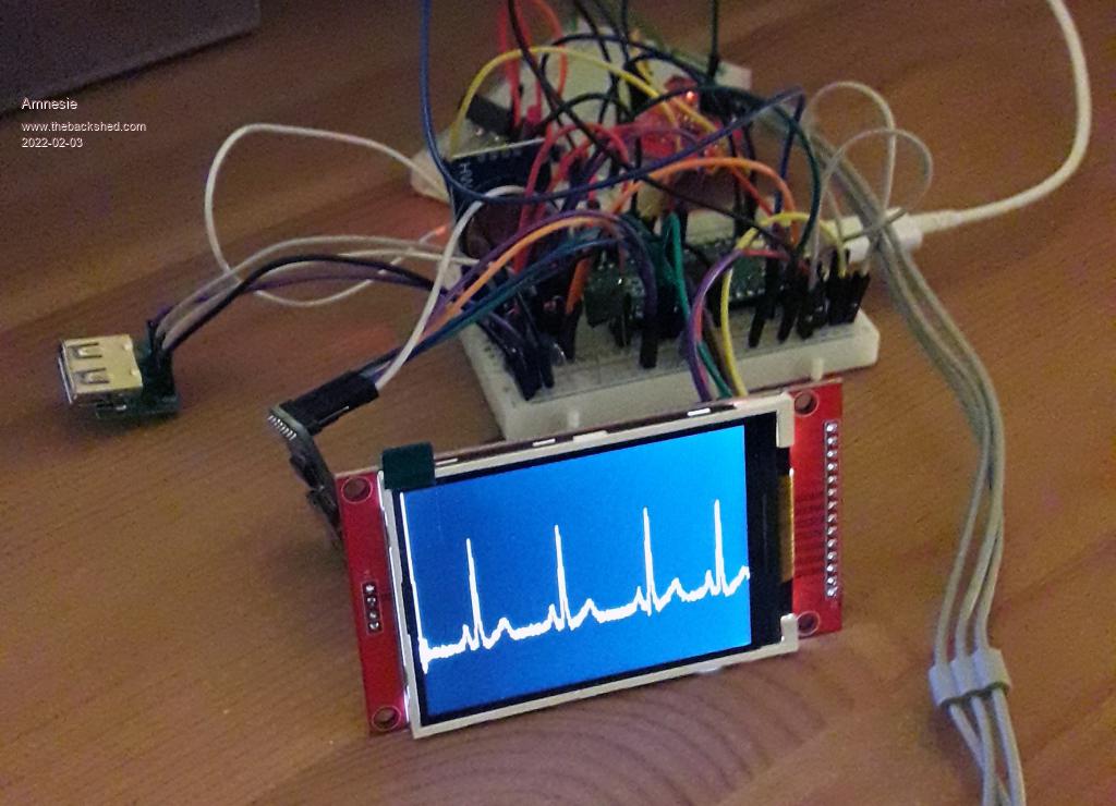 No extra beats on this image :) And ignore the messy work, I already designed a PCB which is on its way from JLC. This is my code so far: SetTick 10, ekg_interrupt SetPin GP28, AIN Do If x>319 Then x=0 EndIf Loop ekg_interrupt: x=x+1 ekg = Pin(GP28) Line x,0,x+10,319,1,BF Line x-1,ekg_alt*100,x,ekg*100,1 ekg_alt = ekg IReturn Yes it is way from perfect, in fact this was just a quick test. I set it up with interrupts for later digital filters (notch filter to get rid of movements and 50hz noise). Also I plan to write the data to the SD card to analyze it with proper ECG software. I just want to thank all people involved in this great conversion to the RaspberryPi Pico! As soon as I implemented digital filters I post my progress. Greetings and keep up this great work and forum! Daniel Edited 2022-02-03 08:14 by Amnesie |
||||
| Andrew_G Guru Joined: 18/10/2016 Location: AustraliaPosts: 883 |
Hi Daniel, A great project! I bet there will be a lot of interest on here. What have you done for sensors - I guess that they are the grey cables bottom right of the picture? Stay well, Andrew |
||||
TassyJim Guru Joined: 07/08/2011 Location: AustraliaPosts: 6538 |
I did one for the original maximite. It told me to go see a doctor (which I did and the maximite was correct) Jim VK7JH MMedit |
||||
| Amnesie Guru Joined: 30/06/2020 Location: GermanyPosts: 757 |
Yes, it is the well known AD8232 sensor for just 3 euro in Germany, which really works great. I am sure it is possible to build a lot of features in this BASIC program. At first I will concentrate on filtering noise, but this should be no problem since there is enough cpu power, it even works on an arduino I just have to port it from C to BASIC language. I am a little bit new to this, so it will be fun as well :) Also planned is SD card output and audio warnings, glad that Peter fixed the wav audio skipping bug in the firmware. Greetings Daniel |
||||
| Amnesie Guru Joined: 30/06/2020 Location: GermanyPosts: 757 |
@ Jim, wow this is interesting, and I hope it is nothing serious! I was a bit nervous because of my extra beats, so my first Arduino version of this ECG was born, with this I discovered the extra beats myself, so I went to a doctor and he just laughed about my little device. But now I have some fun with the picoMite which has way more power... :) This is my designed PCB for general purpose projects for the picoMite.. if everythings works I can upload the gerbers if there is interest. Some features like RTC, KEYBOARD, LCD, SDCARD etc.. are on board. I am not using the onboard SD socket of the display because it is bad quality... The Adafruit breakouts are way better. 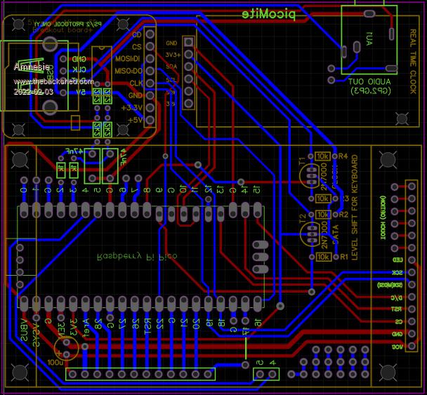 Edited 2022-02-03 09:41 by Amnesie |
||||
| Justplayin Guru Joined: 31/01/2014 Location: United StatesPosts: 330 |
I would be interested in something like this since I suffer from AFib myself. Spent a week in the hospital and had a defibrillator used on me a couple times. Now days I have extra beats and missing beats so it all averages out.  Anyway, it would be nice to be able a watch what is happening beyond the visit to the Doctors office every six months. Anyway, it would be nice to be able a watch what is happening beyond the visit to the Doctors office every six months.--Curtis FYI, defibrillator burns on the chest really hurt! I am not a Mad Scientist... It makes me happy inventing new ways to take over the world!! |
||||
| hitsware2 Guru Joined: 03/08/2019 Location: United StatesPosts: 738 |
Delightfully terse ....  my site |
||||
| Turbo46 Guru Joined: 24/12/2017 Location: AustraliaPosts: 1693 |
You may want to check this out. I have AF too, it gave me a stroke. Luckily a minor one and I quickly made a full recovery. So make sure you do see a doctor. I may have to build one myself. In that post Peter mentions synchronising the sample time with the mains to avoid hum. An active notch filter may be a simpler method. Bill Edit: A save screen would be handy if you see an episode that you want to keep to show your doctor. Edited 2022-02-03 15:45 by Turbo46 Keep safe. Live long and prosper. |
||||
| Plasmamac Guru Joined: 31/01/2019 Location: GermanyPosts: 620 |
Sehr schoen . Neat idea. Plasma |
||||
| Amnesie Guru Joined: 30/06/2020 Location: GermanyPosts: 757 |
@ Bill Yes, this is a good idea! I didn't know Peter did an ECG in 2019! Really interesting. But I am doing my own approach just to learn BASIC a little bit better and I want to use active bi-quad notch filtering like in my Arduino versions (works great!)... Challange is only to port it to BASIC language, but that is the fun part :) I was just amazed how simple BASIC is, a hand full of lines and you got a crude ECG. Greetings Daniel |
||||
| lizby Guru Joined: 17/05/2016 Location: United StatesPosts: 3784 |
Neat indeed. Please do post the gerbers (or wait if you think you have further refinements). And please post a link to your sensors. Which PCB design software did you use? Maybe run MISO with an inline 680R resistor so that a larger SPI 480x320 ILI9488 may be used (although it could be used with MISO not connected as long as BLIT READ or similar isn't wanted--or, perhaps more importantly for this application, SAVE IMAGE). ~ Edited 2022-02-04 00:56 by lizby PicoMite, Armmite F4, SensorKits, MMBasic Hardware, Games, etc. on FOTS |
||||
| Amnesie Guru Joined: 30/06/2020 Location: GermanyPosts: 757 |
Thank you lizby for your advice! I am using easyEDA as "software". I just wanted to post a quick update with my digital filter (there are more to come!) The filter does work really great, there is no noise at all. The next filter I am planning is to make it more resistant against hand and body movements (high pass filter). SetTick 10, ekg_interrupt 'samplerate 100Hz SetPin GP28, AIN SetPin GP25, DOUT CLS c Do If x>319 Then x=0 EndIf Loop ekg_interrupt: x=x+1 ekg = Pin(GP28) a0 = 0.20657128 a1 = 0.21314257 a2 = 0.20657128 b1 = 0.16952595 b2 = 0.09581110 sn_2 = s_n1 s_n1 = s_n s_n = ekg g_n2 = g_n1 g_n1 = g_n g_n = s_n*a0+s_n1*a1+s_n2*a2+g_n1*b1+g_n2*b2 ekg = g_n Line x,0,x+10,319,1,BF Line x-1,ekg_alt*100,x,ekg*100,1 ekg_alt = ekg IReturn I know the screen draw could be better etc, but I am concetrating right now on the plain filter implementation :) Edited 2022-02-04 04:43 by Amnesie |
||||
| Volhout Guru Joined: 05/03/2018 Location: NetherlandsPosts: 5931 |
Hi Amnesie, The heartheat is a small signal that could be drowned in mains hum. By using 100hz sample rate you are almost eliminating the hum, since it is almost synchronous with 50hz mains in Germany. Why not completely eliminate the by sampling at each zero crossing of the mains voltage? That would give a minor fault in heartbeat(0.1% max mains frequency drift) but translate all hum to dc(offset). So only remaining is a simple high pass filter for body movement. Volhout P.S. also ordered a ECG kit, and few new pico's (I ran out of them) since I got interested. Thanks for posting... P.P.S. did you look at the MATH commands, it these could be used to do the filtering faster ? Edited 2022-02-04 17:58 by Volhout PicomiteVGA PETSCII ROBOTS |
||||
| CaptainBoing Guru Joined: 07/09/2016 Location: United KingdomPosts: 2171 |
Interrupt service routines should really be kept as short as possible, even though you don't seem terribly pushed timing-wise a quick hit would be to define the constants a0 to b2 outside the ISR e.g. Const a0 = 0.20657128 Const a1 = 0.21314257 Const a2 = 0.20657128 Const b1 = 0.16952595 Const b2 = 0.09581110 right at the top of your prog. Edited 2022-02-04 18:37 by CaptainBoing |
||||
| Amnesie Guru Joined: 30/06/2020 Location: GermanyPosts: 757 |
Thank you all for advice! Since I am completly new to BASIC this is much appreciated. I will follow your suggestions and keep the ISR as short as possible and check the MATH commands. I encountered already a problem due to this (I think): I tried within the interrupt routine to write the ECG data (100Hz sample rate) to the SD-Card with really bad results, the graph is slower and way more noise is introduced, I think this is the wrong approach anyway (maybe buffering data and then send it to the sd card?). Jim mentioned I could even do a image once I press a button, for example with the SAVE IMAGE "test" command, but always the picture taken is completly white. I tested the command even directly in the prompt, always the same. The whole bmp image is white. But with the ILI9341 TFT I am using it should work?! @ Volhout the idea with the 50hz filtering is good, but in my special case the hum isn't exactly at 50Hz... With this filter constants I've got almost no noise. But of course there are more filter to add anyway (50Hz, 40Hz low pass, 1Hz high pass etc) Thank you all! Edited 2022-02-04 20:11 by Amnesie |
||||
| CaptainBoing Guru Joined: 07/09/2016 Location: United KingdomPosts: 2171 |
everyone here began as something else. Most of the time, advice comes from a loving place. Logging to external storage can be a bit slow and the routines to do so are "blocking" - meaning your program is not running while you are inside of the command to write. Depending how much RAM you have think about buffering everything in memory (an array variable) and writing to disk periodically. You will probably still get those "glitches" but less often. Edited 2022-02-04 21:14 by CaptainBoing |
||||
| phil99 Guru Joined: 11/02/2018 Location: AustraliaPosts: 3291 |
" The whole bmp image is white. But with the ILI9341 TFT I am using it should work?!" Yes it should. It seems like MISO signal isn't getting from the panel to the Pico. On the ILI9341 it is labeled SDO(MISO). The manual shows which pin to use on the Pico. Edited 2022-02-04 21:26 by phil99 |
||||
| Amnesie Guru Joined: 30/06/2020 Location: GermanyPosts: 757 |
Okay this is awkward. On my PCB design I connected it, but on the breadboard I somehow forgot... Thank you! It now perfectly works. |
||||
| Volhout Guru Joined: 05/03/2018 Location: NetherlandsPosts: 5931 |
Hi Amnesie, Standard practise is to keep the interrupt routine as short as possible (short time). Doing math (the digital filtering) on the pico is relatively fast, but would also better be done outside the interrupt routine. But the killer is the LCD drawing. Although the pico potentially could run at 250MHz, the speed for LCD drawing is limitted to the SPI bus speed. So your "block erase" and line draw may cause the delays in the interrupt routine. One question to answer for your project is: do you need immediate visibility of the EKG (ECG) build up or would you be happy with drawing LCD only when you can draw a full screen ? In later case, you could use the ADC to sample 100Hz in the background to a memory array, and once full, restart sampling in the background. In your basic program you would do the digital filtering and display based on data in the memory array. The digital filtering could be done on an array of data using the MATH commands for arrays. (I do this exact same thing for a mains network analyzer showing waveform, fft, based on mains voltage sampled with 4kHz speed in the background). Again, you would loose the live view of the heartbeat this way, so your patient (or yourself) could have died before you see the ECG ;) Volhout PicomiteVGA PETSCII ROBOTS |
||||
| Volhout Guru Joined: 05/03/2018 Location: NetherlandsPosts: 5931 |
Maybe someone knows... I am puzzled... Now I have finally received my picomites, I was curious why it was a problem to save data to the sd card. So I took Amnesie's work and tried to write data to SD card while running the program. And in trying that I ran into problems. This is the code I tried 'elementary ECG(ekg) viewer CLS Dim samples(319) Open "ekg_data.csv" For output As #1 SetTick 10, ekg_interrupt SetPin GP26, AIN Const a0=0.20657128 Const a1=0.21314257 Const a2=0.20657128 Const b1=0.16952595 Const b2=0.09581110 Do If x>319 Then x=0 SetTick pause ekg_interrupt For i=0 To 319 Print #1,Str$(samples(i));"," Next i SetTick resume ekg_interrupt EndIf ' If inti=1 Then ' Print zeit; " ms" ' init=0 ' EndIf Loop While Inkey$="" Close #1 End ekg_interrupt: Timer = 0 'next sample x=x+1 ekg = Pin(GP26) 'digital filter s_n2=s_n1 s_n1=s_n s_n=ekg g_n2=g_n1 g_n1=g_n g_n=s_n*a0+s_n1*a1+s_n2*a2+g_n1*b1+g_n2*b2 ekg=g_n samples(x-1)=ekg 'clear section and write ekg to screen Line x,0,x+10,319,1,BF Line x-1,ekg_alt*100,x,ekg*100,1 ekg_alt = ekg zeit=Timer:inti=1 IReturn I was actually positively surprised that the math and drawing in the interrupt routine only used 25% (2.5ms of 10ms). That is not too bad. But probably not sufficient to write data sample for data sample to sd card. That is why I looked at writing 320 samples at a time, and decided to stop the tick interrupt to do so (at risk of loosing few samples). The settick pause and settick resume do not seem to work as I thought they would Without the settick pause and settick resume it works, but I am not sure if I collect interrupts during the sd card writing (in which case there is also a chance of writing to LCD on the same SPI bus)... maybe a risk of data corruption. Edited 2022-02-27 05:49 by Volhout PicomiteVGA PETSCII ROBOTS |
||||
| The Back Shed's forum code is written, and hosted, in Australia. | © JAQ Software 2026 |
