
|
|
Forum Index : Microcontroller and PC projects : CMM2: It is actually easy to hand-solder the 176-pin ARM CPU...
| Page 1 of 2 |
|||||
| Author | Message | ||||
Grogster Admin Group Joined: 31/12/2012 Location: New ZealandPosts: 9975 |
I have ten boards I had made at JLC, less the ARM processor chip, as they were out of stock. The ARM processor is out of stock basically everywhere, but I have ten chips I ordered from element14 before the stocks were totally depleted, and they have arrived this week, so I thought I would have a go and see just how hard it was - or not - to hand-solder this 176-pin beast. 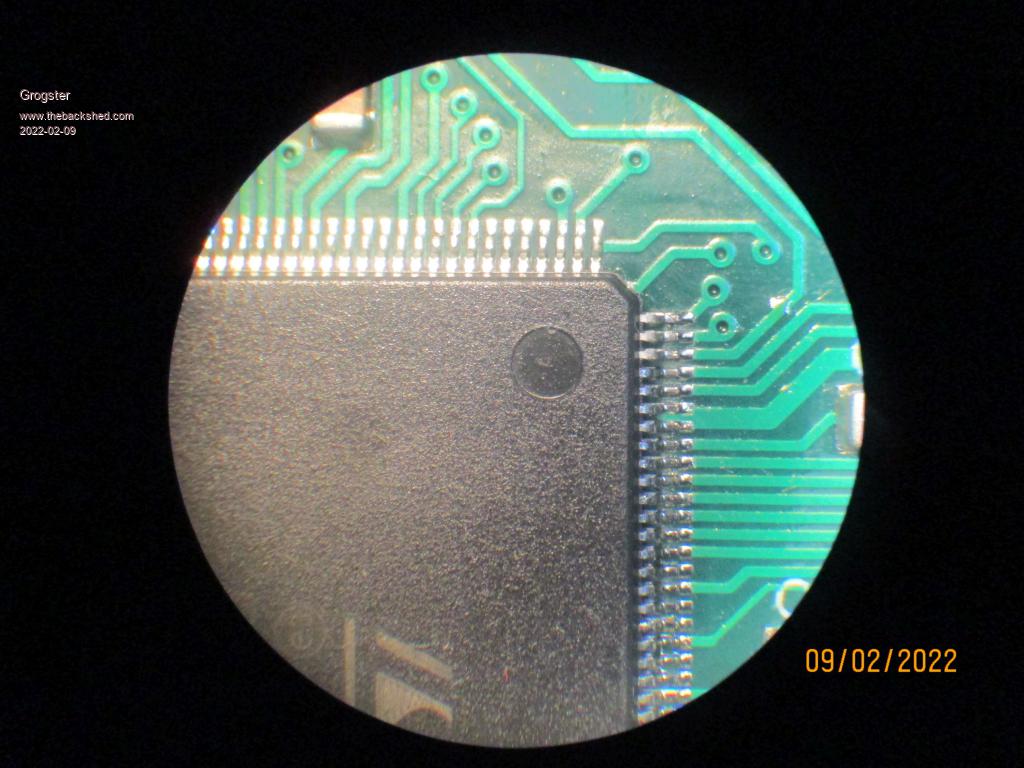 Actually quite easy, using the standard drag-solder technique at 90-degrees to the pins. Can drag-solder each side of the chip in about 5-10 seconds, so the entire beast in less then a minute. This unit programmed fine, and has passes the QC testing, so I will be sending it off to one of my back-order clients in the next few days. I have ten units to build by manually soldering the ARM processor chip, but the first one was easy enough, so I don't expect the others to be any more difficult. JLC were also out of 8MHz crystal oscillator packages, so I had to manually hand-solder that also, but happily, everything worked as expected. Once I send to my back-order list, I will then have seven CMM2 units to sell on my website if anyone is looking for one. Back-orders accepted for these last seven that will be available between now and about this time next year - IF they don't push the delivery time back even more. Smoke makes things work. When the smoke gets out, it stops! |
||||
| Volhout Guru Joined: 05/03/2018 Location: NetherlandsPosts: 5931 |
Perfect soldering !! Absolutely flawless. Did you use leaded solderpaste (looking at the gloss, you did). Or is this the copper based solder? PicomiteVGA PETSCII ROBOTS |
||||
| Mixtel90 Guru Joined: 05/10/2019 Location: United KingdomPosts: 8911 |
That's very nice indeed. Do you use a cup-end bit for drag soldering? Mick Zilog Inside! nascom.info for Nascom & Gemini Preliminary MMBasic docs & my PCB designs |
||||
CircuitGizmos Guru Joined: 08/09/2011 Location: United StatesPosts: 1427 |
Good job, Grogs! I did probably 50 this way. I make a smooth motion across the side with a soldering iron at an angle to the comb of the pins, leading the iron tip with fine solder. Takes seconds. Usually leaves the last two pins bridged, but that is a fast fix. Micromites and Maximites! - Beginning Maximite |
||||
| toml_12953 Guru Joined: 13/02/2015 Location: United StatesPosts: 657 |
Good job! I find lots of liquid flux helps me solder things like that. |
||||
| Grogster Admin Group Joined: 31/12/2012 Location: New ZealandPosts: 9975 |
Thanks for all the nice comments.  I never wanted to hand-solder this beast before in the past, as the shear size of the package and number of pins, gave me nightmares of it being somehow more difficult to solder then smaller pin-package chips. I was totally wrong on that - they are just as easy as the smaller ones, so I was deluding myself there. To answer the questions: - No to solder paste, just standard 60/40 solder on the iron tip. - Standard screwdriver bit, not a well-based or cup-based one, simply as I don't have one. - Yes, plenty of flux. I use CAIG Brand Rosin Soldering Flux gel, as it does not evaporate like liquid flux can before you are ready for it. Once soldered, spray with PCB solvent and using an anti-static brush(and wrist-strap on yourself, naturally), clean off the flux residue to leave a nice clean looking result. I have a roll of 0.38mm 60/40 solder I use for this kind of thing, as with thicker solder, it is way too easy to put too much on the tip, then you get pin-bridging all the way along. 0.38mmm or thinner multicore 60/40 solder is expensive compared to the standard 0.71mm rolls, but it is well worth the expense, as it makes soldering SMD chips especially, much, much easier then with the thicker stuff. Even if you are being very careful, it is just too easy to put too much solder on the tip with the thicker stuff. With 0.38mm solder, and just a tiny bit on the tip, aided with flux, it just flows to where it needs to be, and the surface-tension means it sticks to the pins and board, but does not bridge between pins. As mentioned by CG, with a chip of this size, you do have to top-up your solder about half-way down each side as you run out with that many pins! Would it be narcistic of me to say that I did not bridge a single pin on this first chip?  But pin-bridging is simply a fact of life when hand-soldering 0.5mm pin-pitch, so I expect I was just lucky on the first one!  I did need to reflow a couple of areas that I was not happy with - dab more of flux, tiny bit more solder on tip, and re-drag just that area to get a nice consistent result. I tend to use the "In-and-out" soldering method with SMD chips usually, where you bring the iron in and out in parallel steps to the pins, working your way down, but drag soldering is much faster on a big beast like this chip, so..... I probably should drag-solder more then in-and-out in light of how easy and fast it is with a pretty good success rate!  I used to hate drag-soldering, as I tended to make more bridges then with the in-and-out method, but perhaps I have perfected my technique now! If the chips were still available, I would still get them fitted at factory. You'd be silly NOT to, but circumstances required manual fitting for these ten!  Smoke makes things work. When the smoke gets out, it stops! |
||||
| Tinine Guru Joined: 30/03/2016 Location: United KingdomPosts: 1646 |
Darned impressive, Graeme  "he's more machine than man, now" Craig |
||||
| Tinine Guru Joined: 30/03/2016 Location: United KingdomPosts: 1646 |
Did you ever get Joe-90 over there? His dad would stick him in a machine and program him with someone else's knowledge. If I had that, I'd grab Pete's knowledge/expertise and would stick MMBasic on the Propeller P2. It's the only safe, serious MCU on the market because they have full control over in California. When I think about all the projects that are on-hold, worldwide because people just aren't aware of this awesome device. I just had an idea for a unique product that every performing musician needs Plate is full atm but if I decide to do something....it's Propeller all the way because I would need thousands |
||||
| Mixtel90 Guru Joined: 05/10/2019 Location: United KingdomPosts: 8911 |
"It's the only safe, serious MCU on the market because they have full control over in California." It's the only single-source device that has no competitors so failure of that one source is fatal to any designs using it. I find that to be of concern and it would certainly put me off designing anything serious using it. If it's so attractive, it also makes me wonder *why* there are no competitors - not even from China. Ok, different MCUs that are good at different things, but in many cases a rework of a PCB will allow a different chip to be used, nasty and expensive to do but possible. Not with the Propeller. Another reason to avoid it is that because it's single source your design *could* attract huge licencing fees at some point in the future if it depends on it. Mick Zilog Inside! nascom.info for Nascom & Gemini Preliminary MMBasic docs & my PCB designs |
||||
| Tinine Guru Joined: 30/03/2016 Location: United KingdomPosts: 1646 |
Anyone can have any amount of Parallax P1s without spending a dime with Parallax. How? The whole thing is open source and you program your own (albeit more expensive) device. The same is somewhat true of the P2. The Parallax community were programming and testing the P2 long before P2 silicon existed. Last time I checked, the iPad was single source and no chance to build one's own. Why has no one copied it? Why are countless devs taking forever and a day to make a product work when it could be achieved in hours with MMBasic? So, your sales department receives an order for 10,000 profitable widgets but engineering says no-can-do, we're gonna sit on our hands for a couple of years to see what pans-out? I'm self-employed and need to come up with product. |
||||
| flasherror Senior Member Joined: 07/01/2019 Location: United StatesPosts: 159 |
People are aware of it but with the price at >$14 just for the chip everybody uses cheaper hardware. Like Mixtel90 pointed out there is only a single source (and I'm not sure how Parallax remains in business these days. The world was different when the Basic Stamp 1 was released (no Arduino or open source or cheap China chips/boards) but apart from P2 they don't have anything new and I'm not sure P2 is a sustainable long term product. I hope Parallax remains in business because I have fond memories of Basic Stamps). Also I haven't checked P2 but didn't P1 have no code protection features? Edited 2022-02-11 01:18 by flasherror |
||||
| Mixtel90 Guru Joined: 05/10/2019 Location: United KingdomPosts: 8911 |
It would also help if Parallax could make their chips easier to get. Fine if you are in the US or are a regular user of the big component distributors (so you don't get hit by high carriage charges on low value orders), but there are very few outlets otherwise. Mick Zilog Inside! nascom.info for Nascom & Gemini Preliminary MMBasic docs & my PCB designs |
||||
| Tinine Guru Joined: 30/03/2016 Location: United KingdomPosts: 1646 |
Cost: The lower-powered, 16 year-old P1. 8-32bit CPUs With a few resistors, it has had VGA from day one or composite video to save pins. This requires one of the eight CPUs. Now, CPU only, no external components. Your project requires twelve UARTs all running @115K Baud Can you handle it? Your project is a REAL 4-axis CNC which means 4 servo motors to drive and 4 incremental encoders to read. Can you handle it? A common solution for non-Propellers is to use the LM629. Four would be required for a cost > GBP 200. The P1 can outperform all four of these LM629s, using 6 of its 8 CPUs for a cost <GBP 8 Regarding the "expensive" P2, to my knowledge, the only single-chip to ever handle TWELVE CNC axes is sitting on my desk. That would require >GBP 600 worth of LM629s and the performance isn't even close. Sample accurate coordination of TWELVE axes!!! Or maybe the project requires 56-16 bit DACs or ADCs or PWMs? Still talking single chip! Oh and HDMI All achieved without using a single interrupt and coded in BASIC. Parallax isn't only about the Propellers and Stamp, they are big in the education field and ship a lot of products and kits to schools, etc. I really don't care if no one else gets excited about the Prop. The only reason I have been able to be self employed for 35 years is because I seek out better and faster solutions. This is why I regard MMBasic as one of my secret weapons. The Props don't have code protection per-se but they have techniques that achieve the same thing, to the point that if someone was smart enough to crack it, they wouldn't need your code. The relatively puny LM629 |
||||
lew247 Guru Joined: 23/12/2015 Location: United KingdomPosts: 1709 |
Basic on the Prop P2 |
||||
| Mixtel90 Guru Joined: 05/10/2019 Location: United KingdomPosts: 8911 |
The P1 is currently 9.60 UKP + VAT = 11.52 UKP. 3 Picos would be 3.60 UKP each incl VAT = 10.80 UKP, and easy to get in the UK. (You have 2 *very* fast COM ports on each + 2 PIOs that can be programmed to give 2 more. That's 12 COM ports in total.) The P2 chip only is a bit over 17 UKP +vat = >20 UKP , but it's only available as a SMD part. The RP2040 chip on its own is 0.75 UKP +vat = 0.9 UKP. The Parallax chips are not low cost, but they have their place. It's a bit of a niche one though, when you compare them with a general purpose MCU. It's a bit like comparing a AVR with a PIC optimised for DSP. Mick Zilog Inside! nascom.info for Nascom & Gemini Preliminary MMBasic docs & my PCB designs |
||||
| Tinine Guru Joined: 30/03/2016 Location: United KingdomPosts: 1646 |
Great, so now I can dynamically redirect the incoming data of one port to output on one/several/all ports....Your Picos? But the P2 has 8 processors with shared memory and I/O. One processor can be handling the HDMI and displaying output from the other 7 processors that could be handling 7 independent tasks. Change the value of a global variable in 1 processor and it changes for all processors. Maybe you're only using 3 processors but you have a function that would impact your loop speed...specify "CPU" as part of the function call and the Prop automatically assigns it to an available CPU...grab the result when it's ready. Clearly, if the Propeller was the standard and someone then came up with the Pico, etc., those MCUs would be laughed out the door. There are other similar concepts such as the Xmos (guys from Inmos, Transputer) but they are a nightmare for we mere mortals. The P2's 64 smartpins are like 64 separate controllers in their own right. MMBasic's Pulse command is great for me but imagine specifying a fixed number of pulses at a specified frequency....simply tell the smartpin to get on with it. No need for the processor to be tied up. The list goes on and on  |
||||
| Mixtel90 Guru Joined: 05/10/2019 Location: United KingdomPosts: 8911 |
With the PIO you can do just about anything you can do with a shift register. At the same time, without using any clock cycles, you can "sideset" pins that have nothing to do with the main task. If you want to cross connect ports that's fine (via IO pins - but, if I understand correctly, the P1 has to work like that anyway unless you are happy to wait for the cog scanner to come around again). You could easily serial link three Picos via SPI to get a very fast data transfer between them (5MHz or more SPI clock). The P1 does this anyway, as each cog is isolated from the shared facilities for 7/8ths of the time, taking 16 clock cycles to come around. The Picos would send and receive data between them virtually simultaneously. At the same time they can be generating 16 PWM outputs at 8 different frequencies each. Oh, sorry - your P1 and P2 have no PWM outputs so you'll have to write them. ;) These things are horses for courses. The Pico won't do some of the things that the Parallax chips will and vice versa. Neither is "better" overall - they are very different beasts. Mick Zilog Inside! nascom.info for Nascom & Gemini Preliminary MMBasic docs & my PCB designs |
||||
| Tinine Guru Joined: 30/03/2016 Location: United KingdomPosts: 1646 |
Huh? The 16 counter/timers on the P1 can generate PWM, each with a different frequency. In my case, I generate motor commands @ 19.531KHz for a 12bit resolution (80MHz clock) On the P2, any/all 64 pins can be set/forget PWM and can achieve 16bit (dithered) resolution. How many I2C does the Pico have? P2 can have at least 29 Number of SPIs are only limited by the # of pins Any/all pins can be high speed counters P2 is a chameleon and can be whatever you need it to be. What can the Pico do that the P2 can't? |
||||
| Mixtel90 Guru Joined: 05/10/2019 Location: United KingdomPosts: 8911 |
I'm not comparing the Pico with the P2. Hadn't you noticed? ;) Apart from quoting a price for the chip I've not mentioned it. You don't compare a mini with a ferrari. On price alone (90p vs 20 quid) there's no comparison. The counter timers "can generate" pwm doesn't mean that they are pwm peripherals. You appear to have to do more work on the P1 as all peripherals are "soft". OTOH the pwm peripherals on the Pico are hardware devices and run truly independently of the main system, only having a clock divider. If you must, you can use the PIOs as PWM devices (or I2c, or COM or SPI or anything non-standard). Even the fact that you don't need interrupts is a red herring. If a cog needs to share info with another or trigger an output pin in response to the input signal then you might have 16*number_of_cogs_behind clock cycles before you can put data into the shared ram or output port, then a possible delay while the other cog processes it. The Pico can respond from trigger to output in just a few clock cycles at a clock speed far higher than 80MHz. The PIOs can be programmed to trigger an output on the next clock cycle. They can run at one step per clock. That's fast and IMHO it's very unlikely that even the P2 can match it. Mick Zilog Inside! nascom.info for Nascom & Gemini Preliminary MMBasic docs & my PCB designs |
||||
| flasherror Senior Member Joined: 07/01/2019 Location: United StatesPosts: 159 |
Run MMBasic Anyway to get this conversation back on topic, for those who do SMD soldering like drag soldering by hand, do you use a stereo microscope? Head mounted magnifier? I'd imagine having proper depth perception is important, so you need both eyes working. |
||||
| Page 1 of 2 |
|||||
| The Back Shed's forum code is written, and hosted, in Australia. | © JAQ Software 2026 |
