
|
|
Forum Index : Microcontroller and PC projects : PicoMiteVGA: My prototype build...
| Author | Message | ||||
Grogster Admin Group Joined: 31/12/2012 Location: New ZealandPosts: 9975 |
Hi all.  I have finally finished building and testing my new PM VGA prototype board. 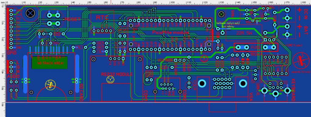 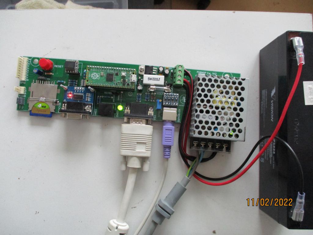 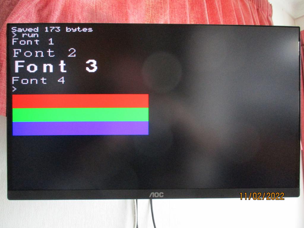 Everything went smoothly, and the VGA output from the PM is very stable and crisp. An amazingly fantastic use of the otherwise unused 2nd core in the RP2040 chip.  Edited 2022-02-11 16:21 by Grogster Smoke makes things work. When the smoke gets out, it stops! |
||||
| Volhout Guru Joined: 05/03/2018 Location: NetherlandsPosts: 5931 |
Hi Grogster, Any schematics for this board ? You are trickle charging the lead acid battery ? What is your audio output circuit ? This looks like something I would build for myself... so that is why I am asking. Regards, Volhout PicomiteVGA PETSCII ROBOTS |
||||
| CaptainBoing Guru Joined: 07/09/2016 Location: United KingdomPosts: 2171 |
|
||||
| Grogster Admin Group Joined: 31/12/2012 Location: New ZealandPosts: 9975 |
Have had quite a few glassed of wine tonight, so sorry if this is mis-spelt.  - No schematic yet, as this is just a prototype so not even sure if it will go past this point. Well, I have a scribbled version, but not in the CAD yet. - Yes, I am trickle-charging the gel-cell via the 22R five watt WW resistor. - Audio output as per Peter's PM schematic. Nothing different there EXCEPT I have added a couple of output coupling capacitors on the audio lines to provide DC isolation to any amplifier stage I plug it into. EDIT: Trying to attach a less-fuzzy PCB image. This might not be possible, as the forum software squeezes images. EDIT: Image deleted. That did not work. Edited 2022-02-11 18:09 by Grogster Smoke makes things work. When the smoke gets out, it stops! |
||||
| Mixtel90 Guru Joined: 05/10/2019 Location: United KingdomPosts: 8911 |
Very nice indeed, Grogster. :) Mick Zilog Inside! nascom.info for Nascom & Gemini Preliminary MMBasic docs & my PCB designs |
||||
lew247 Guru Joined: 23/12/2015 Location: United KingdomPosts: 1709 |
If you use imgbb.com and post it here as a web link it won't resize to upload the picture when you've uploaded the picture choose this  then use this to share the picture link here 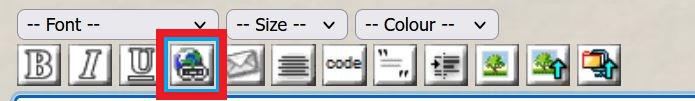 |
||||
| flasherror Senior Member Joined: 07/01/2019 Location: United StatesPosts: 159 |
Neat looking board - what are the PCB dimensions? From the shape it's probably designed to fix some type of enclosure with the battery etc? I have been thinking about using that same RS232 module - did you cross connect RS232 module TX to Pico RX etc or connect "straight" i.e. RX to Pico RX? I cannot find a schematic for this module and have had an experience where an RS485 module did NOT need to be cross connected since the pin labelling was from the MCU's point of view (i.e. connect RX to MCU RX, TX to MCU TX). Edited 2022-02-11 21:21 by flasherror |
||||
| phil99 Guru Joined: 11/02/2018 Location: AustraliaPosts: 3292 |
Tx/Rx inconsistency is annoying, SPI uses MOSI and MISO to eliminate it. For serial I use TX-> & Rx<- or <-Tx & ->Rx, the data flow arrow being more important than the designation. |
||||
| Grogster Admin Group Joined: 31/12/2012 Location: New ZealandPosts: 9975 |
@ lew247 - Excellent idea. I will check that out some more. Standard JPG images upload and resize fine here, but CAD images - even if I upload as a GIF - get resized and compressed, making them fuzzy. I don't care, really, cos as you mention - there are other ways to do it, so..... @ flasherror - I just used the MAX3232 datasheet to find out which pins were connected to the pin-header. These little RS232 modules use pins 11,12,13 & 14 only. I have a schematic for that module on file. If you want a copy, let me know here and I can upload it. On those little modules, TXD is INPUT(from PicoMite) and RXD is OUTPUT(to PicoMite), so it is with respect to the DB9 connector. No level-correction on this one, as being a MAX3232, you can run it at 3v3, so I just run it from the PicoMite 3v3 output pin, and directly connect between the module and the PicoMite COM1 pins. I TOTALLY agree with you on the confusion with serial TX and RX lines. Something that I really like about SPI is the way that CAN'T happen, so long as you know what MISO and MOSI mean! I can't remember how many times I have said to myself: "TXD and RXD with respect to.....which end was it now?" With my own designs, I usually adopt(steal!) the Sparkfun labelling method, and use TXO and RXI type labels. TXO - Transmit out, RXI - Receive in. That CAN be the other way around also(TXI and RXO), but at least that last letter tells you which direction the data should be flowing. But you can still get it wrong with a moments inattention!  EDIT: Forgot to answer your dimensions question. It is 240mm x 60mm, designed to fit into a specific box with battery, yes. I will post a photo here later, of it inside its box. @ phil99 - Agree with everything you said there. Edited 2022-02-12 11:15 by Grogster Smoke makes things work. When the smoke gets out, it stops! |
||||
| Grogster Admin Group Joined: 31/12/2012 Location: New ZealandPosts: 9975 |
CAD drawing external link test: ADD IMAGE button method:  This method does not seem to work, despite pasting in the public link. This is the link I tried to use for the ADD IMAGE button: https://www.dropbox.com/s/2a4sdmleyxea44e/PM_PT_GIF.gif?dl=0 ADD HYPERLINK method: PicoMiteVGA Prototype CAD image Edited 2022-02-12 11:27 by Grogster Smoke makes things work. When the smoke gets out, it stops! |
||||
| Grogster Admin Group Joined: 31/12/2012 Location: New ZealandPosts: 9975 |
Prototype inside its box: 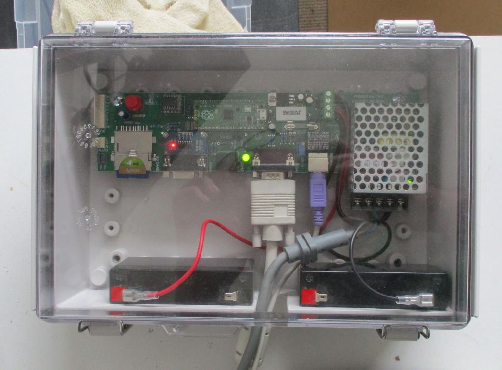 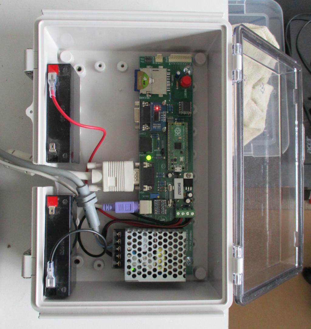 Batteries not yet connected at the 0v point. I'm using 2x 6v gel-cell batteries in series mainly due to lack of space inside the box. Smoke makes things work. When the smoke gets out, it stops! |
||||
| Amnesie Guru Joined: 30/06/2020 Location: GermanyPosts: 757 |
This is a really cool design, I like the idea of the RS232 COM port because you can cover quite long distances! Does it work properly with the picoMite? I am planning to use it, too. For what application do you plan to use this device within this box? Looks interesting. - Daniel Edited 2022-02-12 22:03 by Amnesie |
||||
| Tinine Guru Joined: 30/03/2016 Location: United KingdomPosts: 1646 |
At the risk of being flamed for not being cheap  I have been using the Pico ATX power supplies. I have been using the Pico ATX power supplies.They can be had with 12v or 24v inputs and provide +5v, +3.3v, +12, -12v. I need the +/-12v for my +/- 10v DACs. 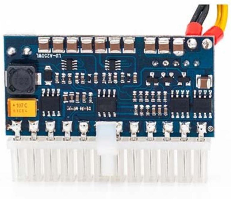 Craig |
||||
| flasherror Senior Member Joined: 07/01/2019 Location: United StatesPosts: 159 |
If it's no trouble could you upload? I have not found an exact schematic for this module. |
||||
| Grogster Admin Group Joined: 31/12/2012 Location: New ZealandPosts: 9975 |
OK, yes, I will find and upload. Watch this thread. Smoke makes things work. When the smoke gets out, it stops! |
||||
| Grogster Admin Group Joined: 31/12/2012 Location: New ZealandPosts: 9975 |
Here you go: EDIT: Image sqeezed so much it is almost impossible to read. Here is an external link to it: Little blue module schematic link... Edited 2022-02-14 09:49 by Grogster Smoke makes things work. When the smoke gets out, it stops! |
||||
| Grogster Admin Group Joined: 31/12/2012 Location: New ZealandPosts: 9975 |
Sorry - forgot to answer this question.  Yes, RS232 port works fine with the PicoMite. The important thing is that you use a module based on the MAX3232 chip. The MAX232 does not run from less then 5v, but the 3232 runs down to 3v minimum, so it is happy at 3v3. I needed an RS323 COM port, as this will be connected to a pager transmitter that has an RS232 interface, so will not work with CMOS 3v3 or TTL 5v. The little blue module converts the 3v3 from the PicoMite to RS232 level, and also 'Down-converts' the RS232 replies to 3v3 for the PicoMite to read. COM2 is a standard TTL(5v) interface for a receiver module. It is level-shifted to 3v3 for the PicoMite via the Level Corrector module. Smoke makes things work. When the smoke gets out, it stops! |
||||
| Amnesie Guru Joined: 30/06/2020 Location: GermanyPosts: 757 |
Hello Grogster, thank you for the hint for the "MAX3232 chip" and NOT the MAX232! This has saved me some time :) |
||||
| The Back Shed's forum code is written, and hosted, in Australia. | © JAQ Software 2026 |
