
|
|
Forum Index : Electronics : Time for a new Warpinverter build - #2
| Author | Message | ||||
| rogerdw Guru Joined: 22/10/2019 Location: AustraliaPosts: 803 |
Thanks Klaus. Yeah I like the look of newly polished copper too but not when it's all tarnished. I like your idea for tinning though, I had not thought of that way. I have a 120W soldering iron I bought for some job many years ago and that worked really well to tin and solder the bars that I soldered to the boards ... a lot better and quicker than I expected. I did start off trying to tin them in a solder bath ... but at only 100mm in diameter it was a bit messy. In the mean time I have fitted heatshrink to much of it to help protect against accidental shorts etc. Maybe I could have masked the connection areas and used a clear laquer on it ... but no going back now. Whoops, I hadn't thought of that either. I'll see how it goes I suppose. My initial thoughts were to keep them flat so the cooling fan can blow up through the centres ... but of course with most of them virtually full of wire, very little air will get through anyway. If it becomes an issue, maybe I can tip a couple on their side. Thanks, it was just some stuff I had lying around and seemed to lend itself to the idea. It would look a lot neater if there was a cap on the channel top and bottom, but I recognised it would be important to keep them cool too ... so I'm leaning towards a barrell fan all the way across the bottom ... blowing air through the capacitor channel as well as past the heatsink and toroids. 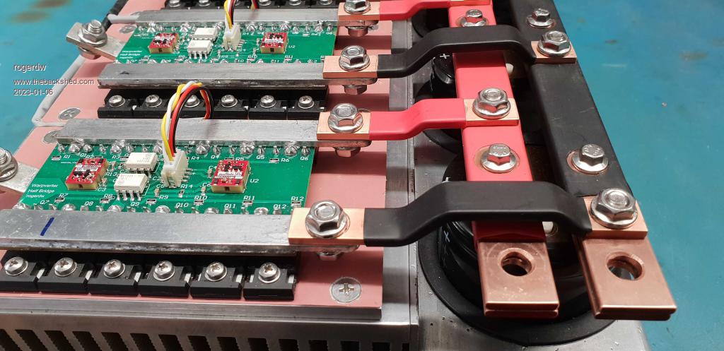 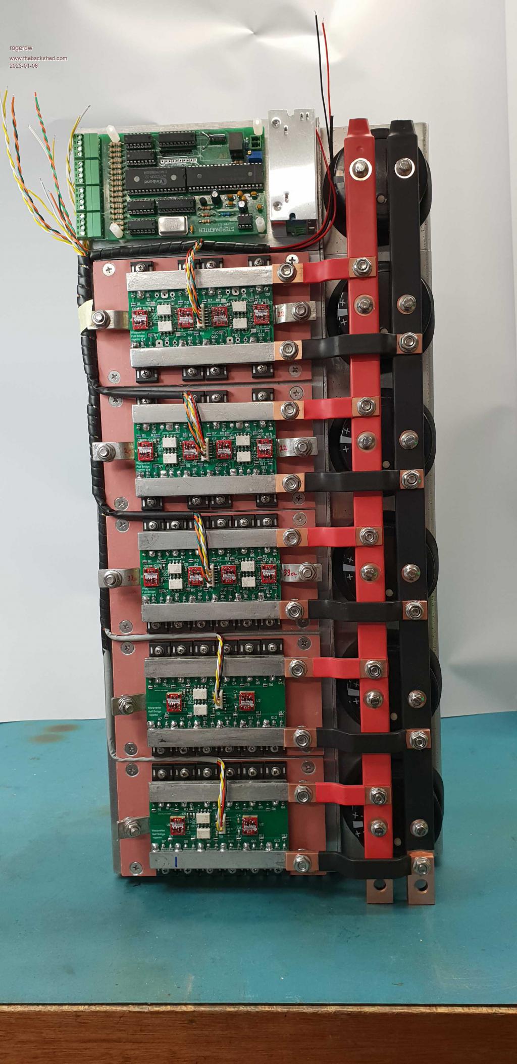 Cheers, Roger |
||||
| wiseguy Guru Joined: 21/06/2018 Location: AustraliaPosts: 1001 |
Roger I would love to just hang it on my wall it is a really wonderful piece of art. I thought Murphy could not be outdone with construction but this must be getting close to it, one of the neatest most serious assemblies I have seen to date. I really hope the final testing goes smoothly, you've set the bar really high - how far away is the testing now? It will be like my first radio-controlled plane build, it took months to build up and it took a fair while on the day to get up the courage to actually fly it (which went well by the way) - trying to build up your confidence! If at first you dont succeed, I suggest you avoid sky diving.... Cheers Mike |
||||
| Murphy's friend Guru Joined: 04/10/2019 Location: AustraliaPosts: 585 |
Ha Roger, your heat shrink solution is very neat indeed. It must have taken you quite some time, you are a patient man who likes to do things better than I can  . .Another suggestion, why did you only bend the half bridge transformer connection busbars at 45 degrees? Connection at all the full bridges would be easier with 45 degree bent busbars as you might need to get a spanner to the bolt head as you tighten the nut. Make sure there is no charge in the caps when you connect up  . .You realise, of course, that you now have to fit the whole caboodle inside a clear Perspex case for future generations to admire  . . |
||||
| rogerdw Guru Joined: 22/10/2019 Location: AustraliaPosts: 803 |
Haha, thanks Mike. I know that after seeing some of Klaus's and your projects and also recently Alston's work too ... that I figured that home made doesn't have to look home made ... and I lifted expectations for what I wanted to build. My Dad often would say that if something is worth doing, it is worth doing well. Of course that has come back to haunt me because I often can't just throw something together, it has to be neat and well done, which obviously takes twice as long. I need to put the second winding on all the transformers yet. Been dragging my feet and really struggle to make the next move. And then hook it all up. I still haven't got my forklift battery yet, my friend had a heart attack and is running a bit slow still ... and I haven't been hassling him because I'm not ready yet anyway. I spoke to him today and should be close by this time next week. And you also seem to have noticed that I'm lacking confidence. Seems the closer I get to finishing a project, the slower I go. Not sure if that's because I'm afraid of what will happen when I hit the go button or what. Need a good talking to, or a shrink. I didn't realise you were into model aircraft ... is that recent or an older hobby? Cheers, Roger |
||||
| rogerdw Guru Joined: 22/10/2019 Location: AustraliaPosts: 803 |
Thanks for the compliments Klaus but as I mentioned above, I've learned a lot from you and the way you build things ... and I've just seen your new battery management system ... and that is a work of art as well as being a very detailed project. The heatshrink was surprisingly easy. I just fitted a piece to each busbar and while it was still hot, pressed into each hole to identify where I needed to cut. I used a wad punch to cut the round holes and a scalpel to cut out the square bits. On the second one, I loosely bolted the short bars in place and cut up close with the scalpel, which was quick, easy and accurate. That's a good question ... it does look a bit odd having them different. I think my reasoning was that the large transformer will have very thick wire connecting (70mm��) ... which will likely be fairly difficult to line up and connect. The smaller transformers will have much smaller wire, so hopefully will be easier to connect to. Will have to wait and see. And the wires joining onto the RHS lugs can face back to the left and avoid rising up close to the positive busbar. If those lugs came out at 45�, it would be difficult to face the wires back the other way. I did make some spare modules, but of course I made them the same, so can't even just swap them out ... and as anal as I can be ... I'm not going to try and rebend them to match. Yes, I am slightly nervous about them ... especially when I use a spanner to tighten the bolts. The bolts have a flange with like a knurled surface, so don't require a lot of force to prevent rotating as you tighten up. Haha yeah, I was wondering if I should put a perspex front on the box ... but probably wont be up to 'code'. Maybe I need to borrow some ideas from the crazy gamers and have a clear case and coloured leds ... or maybe not. 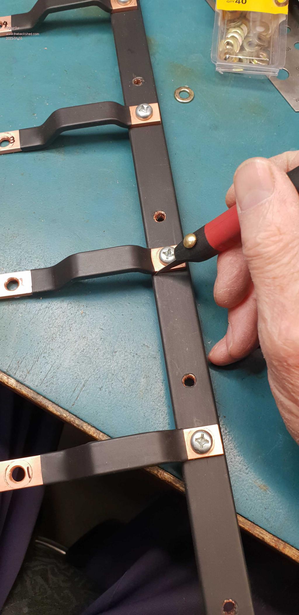 Cheers, Roger |
||||
| KeepIS Guru Joined: 13/10/2014 Location: AustraliaPosts: 1373 |
I'm with Mike, hang it on the wall, then you will never know the stress of hearing your art work go bang  It's all too hard. Mike. |
||||
| rogerdw Guru Joined: 22/10/2019 Location: AustraliaPosts: 803 |
Haha, I have a feeling that's the reason I'm struggling to move forward. Crazy part is I fix stuff for a living ... and I don't have any problem hitting the go button there. If it goes bang, I have another look.  Cheers, Roger |
||||
| wiseguy Guru Joined: 21/06/2018 Location: AustraliaPosts: 1001 |
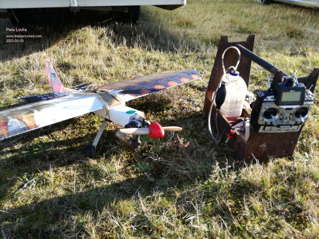
Here is a picture of the plane in question FYI. Just love water flying, the touch and goes are poetry in motion in calm water..... - it is still in one piece. Looking at it again now its a fairly serious bit of hardware. Were you into R/C too ? 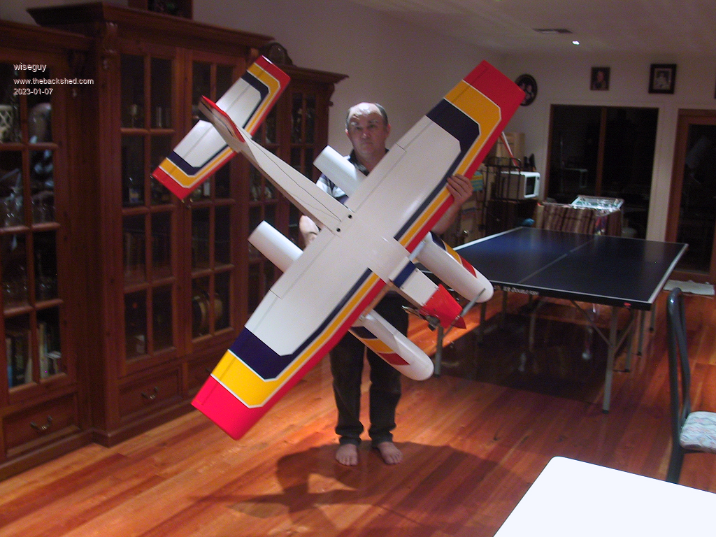 If at first you dont succeed, I suggest you avoid sky diving.... Cheers Mike |
||||
| Murphy's friend Guru Joined: 04/10/2019 Location: AustraliaPosts: 585 |
Wow Mike, that is one serious model plane, almost big enough to hitch a ride on. How long can it stay airborne before running out of fuel? What size is that motor? |
||||
| wiseguy Guru Joined: 21/06/2018 Location: AustraliaPosts: 1001 |
Hi Klaus the motor is an OS91 4 stroke and doing touch and goes on floats with an occasional loop and barrel roll around 25 minutes continuous. Even though most at the club are on full electric - which are equal in performance and duration these days, I think I get a small high from methanol and castor oil fumes lol. I just checked and quite a few years ago a mate took a short clip and posted it on youtube much to my surprise it's still there watch That day was blowing a gale but I still took a chance and flew it, from stopped to flying in a few meters - trying to avoid the rough water. Sorry Roger, bit off topic, you can have your thread back now �  Edited 2023-01-07 18:18 by wiseguy If at first you dont succeed, I suggest you avoid sky diving.... Cheers Mike |
||||
| rogerdw Guru Joined: 22/10/2019 Location: AustraliaPosts: 803 |
You're right it is definitely a serious bit of hardware, very impressive. And no, I was never into R/C. We did build a few sailplanes as kids but that was before R/C. Then motorcycles took over. Haha, thanks. I did watch the video but then I watched the next two that came up ... there goes another hour and a half. Any excuse to not get on with the job!!! Cheers, Roger |
||||
| Murphy's friend Guru Joined: 04/10/2019 Location: AustraliaPosts: 585 |
I admire your work ethic Roger , I was watching Utube vids for the rest of the evening after seeing Mike's. Would have liked to see the plane land, whether he had to swim to fetch it  . . |
||||
| rogerdw Guru Joined: 22/10/2019 Location: AustraliaPosts: 803 |
Yeah, I kept wondering if he had a boat handy in case of forced landing or something like that. Cheers, Roger |
||||
| wiseguy Guru Joined: 21/06/2018 Location: AustraliaPosts: 1001 |
Very perceptive Roger, I always had a boat or a paddle board handy just in case. The only exception to this was once I flew off Lake Meningie with a good steady on-shore breeze blowing and no boat/board with me. In hind-sight I never considered a sudden wind change and I am not a strong enough swimmer to risk going after it. Luckily that plane was always able to land and taxi back to where I was & the boat was never required to fetch it - not so for all my planes though. I'll see if I can find a short clip of what we call a "greaser" gentle landing. Hey it might inspire others to something not inverter related, but a caveat that there is also similar potential for a spectacular finish  If at first you dont succeed, I suggest you avoid sky diving.... Cheers Mike |
||||
Revlac Guru Joined: 31/12/2016 Location: AustraliaPosts: 961 |
My thoughts exactly, nice work BTW.  Cheers Aaron Off The Grid |
||||
| Pete Locke Senior Member Joined: 26/06/2013 Location: New ZealandPosts: 179 |
 RC is one of my pass times. Used to fly light aircraft as a hobby, but after 25 years doing that, the shine went off it. RC is a GREAT, and a lot cheaper way to be in the air. Can't compete with Mike's amazing creation. Mine are made from PVC down pipe with the wings formed using real estate signs, and a yard stick (who remembers those...) for the spar. Pulled along with a 0.46 glow engine. Very stable and low cost sport plane  . Great fun. . Great fun.Edited 2023-01-10 16:26 by Pete Locke |
||||
| solarsim Newbie Joined: 10/01/2021 Location: AustraliaPosts: 10 |
Hi guys... i have been inspired by all the work that you have done... lovely build rogerdw ... and so much help from so many including warp. I am doing my own build of around 48v system and just wanted to share some stuff right here. So... I have kicked off from tony's warpverter and rolled my own version. I used jlpcb to squeeze the control board onto a 4" x 4" footprint including 3 isolated converters on the same panel.. It does use some surface mount, but I am pretty confident that there wont be any need for much rework (time will tell?) and I can just swap a whole control board if needed (you get 5 for around $10 as just pcbs) .. I paid a bit extra for jlpcb to mount a lot of the surface mount components anyway, but through hole for the big eeprom and a-d converter chips. My isolated gate driver supplies (15-16v in, 15v out6) use a 2 transistor bose oscillator, a bd140 , small torroid, and one timing cap.. guaranteed startup. The secondary has a tl431 regulator, and the whole deal is a constant drain on a 16v or so input voltage using about 0.9w to produce about 0.5w (15v @30mA) isolated output. Anyway i have tested it really well including ltspice simulation, a prototype and final commit to a small mostly surface mount version on the main 4"x4" board -- need 16 of these. This does assume that there will need to be a step down dc converter from the 48 volts or whatever to about 16v d.c. at around 1 amp. I wanted to avoid any chinese converters so will probably use a roman black discrete 2 transistor design for that. I wanted to really visualize the eeprom file, so I simulated all of the hex bytes using Libreoffice - calc (I am a bit of a linux person) .. and some basic code in behind the spreadsheet. So you can see the effect for a given system voltage (42v) of varying the actual voltage on the stepped waveforms. Sheet one has the 40 +0 +40 control bytes and a graphic of them all adding up to an 81 step pk-pk stepped sine wave. Sheet 2 lets you put in a particular voltage and see a graphic of the actual steps that would be driven to the final output. You can even compare for example a 42v input and an 84v on two halves of the same wave. There are macro buttons to push. Sheet 3 generates (from a voltage and step size ) 32 full waveforms , and then writes it to a text file.. you then use a command line to convert the rom.txt to a rom.bin for burning... It's really interesting to see the frequency of each step level for 32 slightly increasing input voltages on one page .. it really brings home how increasing voltage inputs reduces the number of steps....and that's kind of where I am up to. Next step will be the transformers. cheers solar sim and a bit thanks to all of that inspiration out there... poida, mack,tinker, warpspeed, wiseguy, murphy, oztules, and all of the wonderful backshed community Now I hope I can manage to attach some files (3 of each of these) |
||||
| solarsim Newbie Joined: 10/01/2021 Location: AustraliaPosts: 10 |
solar-sim-files.zip |
||||
| rogerdw Guru Joined: 22/10/2019 Location: AustraliaPosts: 803 |
Thanks solarsim and great effort on your part. Never ceases to amaze me the level of skill and expertise of you guys out there ... and also all the different ways of solving problems. I can't believe all the work you've put into the spreadsheet, not that I understand much of it ... but glad there's a way to simulate some of this stuff ... and also create files for different configurations. And good luck with your transformers now. Cheers, Roger |
||||
| solarsim Newbie Joined: 10/01/2021 Location: AustraliaPosts: 10 |
|
||||
