
|
|
Forum Index : Microcontroller and PC projects : PicoMite: PicoGAME VGA development
| Author | Message | ||||
| thwill Guru Joined: 16/09/2019 Location: United KingdomPosts: 3865 |
Thanks. I must be learning as I wondered if it was something like that, or otherwise parasitic on one of the other decoupling caps on the board. Best wishes, Tom Game*Mite, CMM2 Welcome Tape, Creaky old text adventures |
||||
| thwill Guru Joined: 16/09/2019 Location: United KingdomPosts: 3865 |
Mick, is the SD card module meant to be soldered in "upside down", i.e. with its SMD components pointing towards the PCB? Have you posted a photo of a constructed prototype that I've missed? Best wishes, Tom Game*Mite, CMM2 Welcome Tape, Creaky old text adventures |
||||
| Mixtel90 Guru Joined: 05/10/2019 Location: United KingdomPosts: 5770 |
Yes, it's upside down. :) Looks a little odd, but in practice it doesn't matter. Here's the "Normal" one: 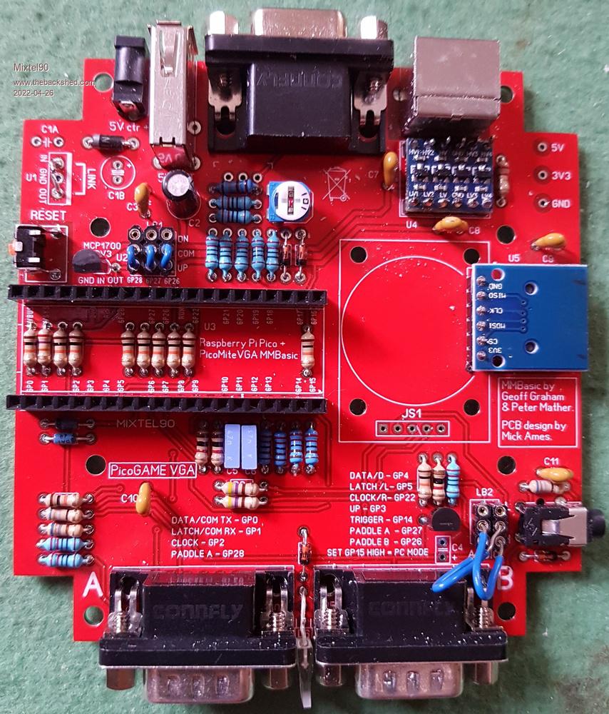 Here's the board mods, but only done on the "other" one. The crossed out mod is to do with re-enabling the SMPS so ignore it. The two crossed over black wires reverse the polarity of the USB-A socket, the rest fix the colours. 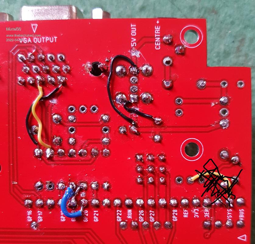 Mick Zilog Inside! nascom.info for Nascom & Gemini Preliminary MMBasic docs & my PCB designs |
||||
| thwill Guru Joined: 16/09/2019 Location: United KingdomPosts: 3865 |
Thanks Mick, very helpful. I've got all the low-lying parts soldered in now, so soon have it working I hope. Best wishes, Tom Game*Mite, CMM2 Welcome Tape, Creaky old text adventures |
||||
| Mixtel90 Guru Joined: 05/10/2019 Location: United KingdomPosts: 5770 |
It's not bad to build, just a bit messy - the joy of prototypes. :) Perhaps just a little cramped in a couple of places but if I can manage it then most people probably can. Works nicely though. I'm currently putting a test program together that does a test of the colours, I/O etc. I'll probably post it eventually. Incidentally, I've had those controllers working fine down to a pulse length of 5us. I didn't try any shorter so they might read even faster. Mick Zilog Inside! nascom.info for Nascom & Gemini Preliminary MMBasic docs & my PCB designs |
||||
| thwill Guru Joined: 16/09/2019 Location: United KingdomPosts: 3865 |
It seems I am determined to build this thing from the wrong parts. How important is the 100 nF capacitor type for C3, C7, etc. ? It turns out the ones I bought are monolithic rather than multilayer ceramic. I also have some nominally 100 nF terracotta coloured disk capacitors, I say nominally because they all seem to test in the 50-80 nF range. Best wishes, Tom Game*Mite, CMM2 Welcome Tape, Creaky old text adventures |
||||
| Mixtel90 Guru Joined: 05/10/2019 Location: United KingdomPosts: 5770 |
Anything around that will do. They are only supply decoupling so they are very non-critical. I've used 100s of disc ceramics for that job - the only reason I didn't use them here is that they can be a bit fragile if you catch them. Value is non-critical too. It'll probably work without them - I was playing safe. :) Mick Zilog Inside! nascom.info for Nascom & Gemini Preliminary MMBasic docs & my PCB designs |
||||
| thwill Guru Joined: 16/09/2019 Location: United KingdomPosts: 3865 |
It lives: 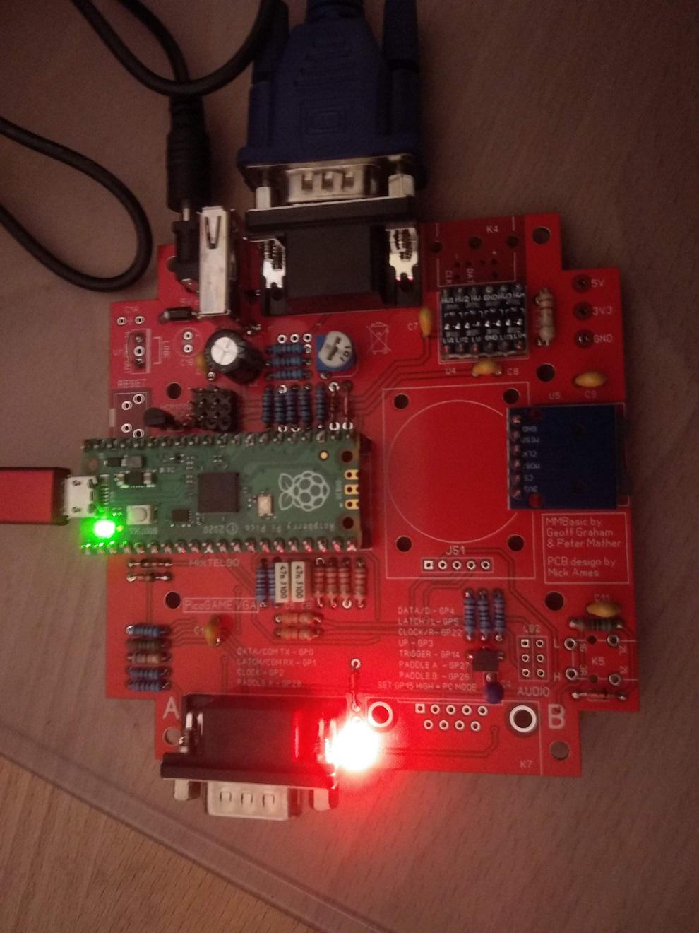 It's missing a few bits - I have them but realised I could get it running without. Thanks Mick, Tom. Game*Mite, CMM2 Welcome Tape, Creaky old text adventures |
||||
| Mixtel90 Guru Joined: 05/10/2019 Location: United KingdomPosts: 5770 |
Excellent! :) I see that you put your DB9 on Port A, which is actually the secondary port on the prototype board. It doesn't matter if you are using a controller though. I'm doing some documentation at the moment, getting the construction package for the next version ready. I decided that so much has happened on it that it deserved a new sub-version all of its own, so now it's officially Version 1.4. 1.2 was the original "new", debugged version and 1.3 was the big A-B swap which then triggered several other positive changes. (Thinks... The secondary port has the "networking" pins on GP4 and GP5, COM2, which are also I2C. You could plug another board with a second PicoMite into Port B and talk to it using either of those - and another pin as an interrupt line if desired.) . Edited 2022-04-27 16:39 by Mixtel90 Mick Zilog Inside! nascom.info for Nascom & Gemini Preliminary MMBasic docs & my PCB designs |
||||
| Volhout Guru Joined: 05/03/2018 Location: NetherlandsPosts: 3589 |
Hey Tom, It is true that energy is expensive, but if you work through the night to get the board working, it is okay to turn on the light when you take a picture....;) PicomiteVGA PETSCII ROBOTS |
||||
| Mixtel90 Guru Joined: 05/10/2019 Location: United KingdomPosts: 5770 |
Light? You were lucky! When I were a lad we didn't have light! There was 19 of us all had to get up as soon as it were light enough to see and go to bed when it got too dark to work in't mill any more. I truly admire his dedication, Volhout. :) Mick Zilog Inside! nascom.info for Nascom & Gemini Preliminary MMBasic docs & my PCB designs |
||||
| thwill Guru Joined: 16/09/2019 Location: United KingdomPosts: 3865 |
It was on, but the camera on my phone has always been a bit sh*t and I just wanted to document my "success" before going to bed. Anyway, can I have some help troubleshooting the PS/2 keyboard connection which isn't working: 1. When I plug it in to the PicoGAME VGA it briefly lights all its LEDs (power, caps-lock, num-lock - I think) and then goes dark and unresponsive. 2. Powered from my wall-wart the 5V line of the board is only reading ~4 V; there is 4.8 V entering the board and it's losing ~0.8v across D1. I've also tried feeding it from my Raspberry Pi in which case the 5V line is reading ~4.3V; there is 5V entering the board and it's losing ~0.7V across D1. 3. The PS/2 keyboard does work on my CMM1. 4. Note that the silk-screen on the PCB and the schematic for the U4 Level Shifter do not match - GND and HV/LV are transposed ... I believe the silk-screen is correct as that matches the component - in which case any chance of an updated schematic so as there is one less thing confusing me. Best wishes, Tom Game*Mite, CMM2 Welcome Tape, Creaky old text adventures |
||||
| Mixtel90 Guru Joined: 05/10/2019 Location: United KingdomPosts: 5770 |
Sounds like your 5V is low. Try shorting out D1 for a start. That will gain you a bit. Is D1 a Schottky type? The level shifter is the same mosfet circuit that's used all over the place. It's just convenient having four of them on a little module. On the PCB the level shifter must have LV1 at the bottom, left position. The silkscreen is correct. I've only labelled LV1 and HV4 on the new board. No space for anything else. :) I don't think I'll re-issue the prototype schematic, there's no real need to as you've already sorted out that bit of confusion :) I'll definitely correct it for the new version 1.4 though. Mick Zilog Inside! nascom.info for Nascom & Gemini Preliminary MMBasic docs & my PCB designs |
||||
| thwill Guru Joined: 16/09/2019 Location: United KingdomPosts: 3865 |
Great, that did the trick. No, it was a 1N4001; the BOM says "You can usually get away with a ..." and it's what I had in stock. I've ordered some 1N5818's, but perhaps safer if you removed the 1N4001 alternative from the BOM in case anyone else has a PS/2 keyboard like mine - a new Perixx PERIBOARD-409P. Best wishes, Tom Game*Mite, CMM2 Welcome Tape, Creaky old text adventures |
||||
| Mixtel90 Guru Joined: 05/10/2019 Location: United KingdomPosts: 5770 |
A 1N4001 will certainly work with my PS/2 keyboard - I'm using one on one board. :) It may well have worked with yours if your incoming supply had been about 5V5 (which I've seen from some supplies when at low current). Unfortunately, not all PS/2 equipment will operate at low voltages (mine is fine at 3V3 and it's pretty old). I'd already removed that alternative as you suggest though - I preempted you last night. :) Strangely enough, one of my first problems with a prototype board was that the keyboard didn't work. Took me ages to discover that I hadn't soldered a joint and it had no supply.... Mick Zilog Inside! nascom.info for Nascom & Gemini Preliminary MMBasic docs & my PCB designs |
||||
| phil99 Guru Joined: 11/02/2018 Location: AustraliaPosts: 1813 |
@thwill It looks like you have an actual 5V keyboard, and thus requires 4.5 to 5.5V. Most are 3V compatible which is possibly why the 1N4001 worked for Mixtel90. I tested 5 and only one very old HP KB needed 5V. |
||||
| thwill Guru Joined: 16/09/2019 Location: United KingdomPosts: 3865 |
Looks that way. I'm a little suprised given it's a "new" product, maybe they tried too hard to actually match the PS/2 standard ? I'm a little concerned that even with the correct diode the voltage may be just the wrong side of marginal unless I use a better quality wall-wart; I was hoping to use the ones in the multi-socket at my workbench. Mick, what is that diode protecting, is it in-case U1 is installed or does it have another purpose ? Best wishes, Tom Game*Mite, CMM2 Welcome Tape, Creaky old text adventures |
||||
| Volhout Guru Joined: 05/03/2018 Location: NetherlandsPosts: 3589 |
Tom, you started out with 4.8v, where typical 5v supplies are 5 or slightly higher. That makes things worse. D1 is there to protect against wrong polarity, kind of essentiel when power is delivered through a jack plug, since there are so many differen supplies out there. In your case you may be helped with replacing D1 with a SB140 shottky diode. That will drop roughly 200mv where the 1n4001 will do 0.7 or 0.8v PicomiteVGA PETSCII ROBOTS |
||||
| Mixtel90 Guru Joined: 05/10/2019 Location: United KingdomPosts: 5770 |
If you have a "pregnant plug" power supply that you can dedicate to the PicoGAME - especially if you put the little barrel jack on it so that you don't confuse it with something else - then you could *fairly* safely do away with D1. OTOH, if you are connecting to the terminals of a power supply then D1 is essential. Also, if you have a USB-A to barrel jack lead for power then you are also probably safe (and can do away with D1) as very few USB-A sockets will have the wrong polarity on them. :) Mick Zilog Inside! nascom.info for Nascom & Gemini Preliminary MMBasic docs & my PCB designs |
||||
| Mixtel90 Guru Joined: 05/10/2019 Location: United KingdomPosts: 5770 |
A couple of BASIC files to play with on your new toy. BASfiles proto.zip Mick Zilog Inside! nascom.info for Nascom & Gemini Preliminary MMBasic docs & my PCB designs |
||||
