
|
|
Forum Index : Microcontroller and PC projects : PicoMite: PicoGAME VGA development
| Author | Message | ||||
| Mixtel90 Guru Joined: 05/10/2019 Location: United KingdomPosts: 5770 |
Regarding audio quality on this PCB - basically, providing it makes a noise and isn't too objectionable when you are 18ins away from cheap desktop speakers then it's probably fine. :) It's nice if it's fairly quiet noise-wise - especially in headphones. I've tried: The "standard" filter with linear regulator. Low level output was good. Headphones were good but a bit quiet via the filter. Using just resistors they were better and I'd say acceptable with 470R. The "standard" filter with SMPS. Low level not bad, but some hash. Not too horrible with headphones via the filter. Headphones with resistors too noisy. Had to increase values and still poor. Volhout's filter with linear regulator. Low level output good. Headphones quieter via the filter, but quality nice. Headphones via resistors were louder than expected (I suspect the filter places less load on the pin, resulting in more headphone drive). Volhout's filter with SMPS. Low level output good - about the same as linear regulator. Headphones louder and noisier - no good. Volhout's emitter follower. Disaster. Plenty of volume, but very noisy. It gives a much better impedance match but that allows any digital noise to also be amplified. It was especially poor with the SMPS, which is probably putting all sorts of rubbish on all the supply lines. I decided that it simply wasn't needed as an I/O pin and a resistor is near enough - and uses a lot less board space. Conclusion. I like the emitter follower concept as it gives better control over the headphones. Unfortunately it would definitely need a potentiometer volume control and there isn't space. A series resistor doesn't help the bass response, but 470R-680R isn't too bad and, with the right source material, can sound pretty good. Low level output seems to be fine, no matter which filter is used (I didn't test it properly though, I admit. I haven't got an amplifier and speakers in this room). It seems better with a linear regulator, which is why I recommend one. . Mick Zilog Inside! nascom.info for Nascom & Gemini Preliminary MMBasic docs & my PCB designs |
||||
| Volhout Guru Joined: 05/03/2018 Location: NetherlandsPosts: 3589 |
Hi Mick, Yeah, there is a lot to experiment. And the switchmode PSU is far from ideal. Reason I am investigating this (previous suggestions like the emitter follower where designed around the DAC in the Armmite F4 and CMM2). This (with 44.1kHz base frequency in the PWM) is a total different beast. If you do nothing about the 44.1kHz, your amplifier (tweeters) will be driven peak-peak with 44.1kHz. And it is depending on the filters inside the audio amplifier how much of it is attenuated. Also headphones... and your cat will stay away from you when you use these on picomite. Cats heat the 44kHz (I don't). And to them the 44.1kHz is louder than anything in we hear. The 1k/47nf filter will attenuate the 44kHz with roughly 20dB (10 times attenuation), but the audio spectrum starts to roll off at 1kHz. 10kHz is -10dB (blue line) This may be useable. But with some more passive components you can achieve better (green, red line). Just playing. My goal would be to get the 44.1kHz at 1%, and a spectrum up to 8 or 10kHz -3dB. That would give a very good audio quality if you would feed it music from the SD card. And it would be in some way compatible with the 11 bits that we have in customer satisfaction. It won't get to CD quality anyway, but I like to get it close. Similar I will look at the VGA sync signals. These at directly driven into the VGA cable. Technically that is possible (proven) but some impedance matchin (serial resistor) may lower the ringing that is bleeding into the audio circuits. 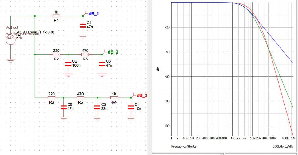 Edited 2022-04-29 17:26 by Volhout PicomiteVGA PETSCII ROBOTS |
||||
| Volhout Guru Joined: 05/03/2018 Location: NetherlandsPosts: 3589 |
I guess this will be my basic circuit when I start working on the other issues (the red line). Can drive a headset. 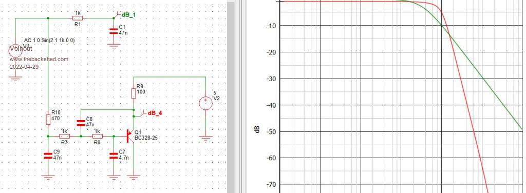 Edited 2022-04-29 18:31 by Volhout PicomiteVGA PETSCII ROBOTS |
||||
| thwill Guru Joined: 16/09/2019 Location: United KingdomPosts: 3865 |
@phil99, @Volhout, Thanks for your suggestions regarding my USB power supply, they sound dangerously close to DIY and my motto/history in that respect is "measure 3 times and then still cock it up", something I don't intend to practice with 240V. For the moment I'm getting by with the PCB diode shorted out and it is anyway time to get back to some programming. One thing I have noticed is that without the PCB attached the USB gives 4.95V, but with it attached it gives 4.8V (measured where the power supply comes into the board), is that a thing ? EDIT: Have just installed 1N5818 schottky diode and that has increased the 5V line to 4.45V which whilst still marginal does appear to run the keyboard - most of the time - occasionally it doesn't, but pressing the reset button on the PCB seems to fix it in those cases. EDIT-2: Ironically in an example of inventory failure I've just uncovered a bag of ~100 x 1N5817, it looks like they would have done the job too. Best wishes, Tom Edited 2022-04-29 20:52 by thwill Game*Mite, CMM2 Welcome Tape, Creaky old text adventures |
||||
| phil99 Guru Joined: 11/02/2018 Location: AustraliaPosts: 1813 |
"One thing I have noticed is that without the PCB attached the USB gives 4.95V, but with it attached it gives 4.8V (measured where the power supply comes into the board), is that a thing ?" Yes. I should have twigged earlier, its the USB cable. Some are mostly plastic and very little copper. Some time ago I had one with excessive resistance and had to bin it. Try another lead and see if that helps. |
||||
| Mixtel90 Guru Joined: 05/10/2019 Location: United KingdomPosts: 5770 |
I have very little bench space most of the time, so I came up with a creative idea. I use one of these modules in a plastic box, with a barrel jack on the back and terminals on the top. I can then plug in a laptop power supply (which can stay on the floor) and get a variable voltage, variable current output with a power switch. I need my glasses on to set it (the text is small) and it's a bit clunky to use, but it's cheap and it works well. Mick Zilog Inside! nascom.info for Nascom & Gemini Preliminary MMBasic docs & my PCB designs |
||||
| thwill Guru Joined: 16/09/2019 Location: United KingdomPosts: 3865 |
Both measurements were taken at the jack end with the USB <-> Jack cable plugged in so I'm not sure its crappyness can explain why the V was lower with the PCB connected - unless I'm missing something. The cable itself is the only USB <-> Jack I've got and is indeed cheap and Chinese but I suspect that most cables of this type are? The measured resistance is < 1R, but I don't know how accurate my Multimeter is for such low resistances. Coincidentally an electronics engineer friend expressed the opinion at the weekend that Chinese Volts and Amps were not the same as "Western" Volts and Amps  . .Neat. I have a cheap Duratool single-output linear bench supply (D03233). The LCD diplay on the one buck-boost supply I have failed almost immediately, but otherwise it seemed to work the last time I tried it. Anyway, with the diode replaced the keyboard is working (for a certain definition thereof) with the PicoGAME powered from that USB cable/socket so let's not spend any more cycles on this. Thanks for your help and advice, Tom Game*Mite, CMM2 Welcome Tape, Creaky old text adventures |
||||
| lizby Guru Joined: 17/05/2016 Location: United StatesPosts: 3027 |
+1 for that gadget. A handy little variable supply with the emphasis on "little". PicoMite, Armmite F4, SensorKits, MMBasic Hardware, Games, etc. on fruitoftheshed |
||||
| Mixtel90 Guru Joined: 05/10/2019 Location: United KingdomPosts: 5770 |
It's not exactly huge. lol! 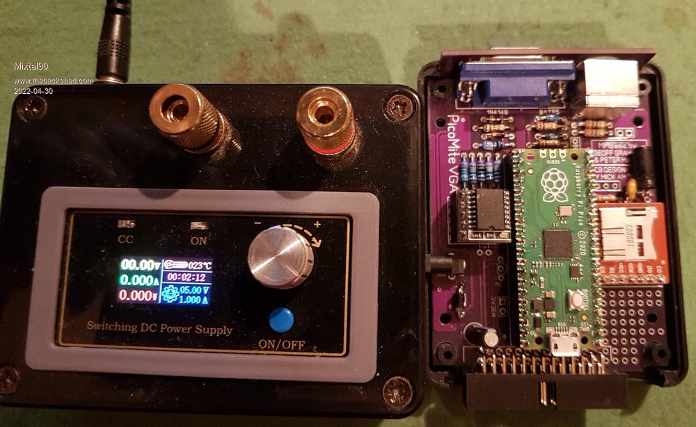 Mick Zilog Inside! nascom.info for Nascom & Gemini Preliminary MMBasic docs & my PCB designs |
||||
| phil99 Guru Joined: 11/02/2018 Location: AustraliaPosts: 1813 |
@Thwill "Both measurements were taken at the jack end with the USB <-> Jack cable plugged in so I'm not sure its crappyness can explain why the V was lower with the PCB connected - unless I'm missing something." When there is no load there will be no voltage drop across the resistance. When you connect the PCB it is drawing current and causing a voltage drop. To see if the drop is due to the cable or the power supply, plug in a second USB device (preferably one that draws over 100mA) while measuring the voltage at the jack (PCB not connected). If there is no change the power supply is ok and the cable remains suspect. Edit. Your CMM1 may provide sufficient load, perhaps? Edited 2022-04-30 10:45 by phil99 |
||||
| Mixtel90 Guru Joined: 05/10/2019 Location: United KingdomPosts: 5770 |
My version 1.4 boards (in Glorious Techniblue) are finished and on their way. :) Sometimes I find it difficult to believe JLCPCB turn-around times. :) Mick Zilog Inside! nascom.info for Nascom & Gemini Preliminary MMBasic docs & my PCB designs |
||||
| Turbo46 Guru Joined: 24/12/2017 Location: AustraliaPosts: 1595 |
@Mick, I'm not sure that I will get any of your VGA game boards but would you consider a game daughter board for Peter's VGA board that would provide the facilities that yours provides that are missing from that board? I'm thinking of a board that would end parallel with the back of the mother board (or the front) so the sockets could fit in a back or front panel. It could plug half into one of the Pico sockets and half in the other for stability if needed. Bill Keep safe. Live long and prosper. |
||||
| Mixtel90 Guru Joined: 05/10/2019 Location: United KingdomPosts: 5770 |
I'm not sure that I would get (or even could get) a board to fit Peter's. We use different software with incompatible file formats. :) Mick Zilog Inside! nascom.info for Nascom & Gemini Preliminary MMBasic docs & my PCB designs |
||||
| thwill Guru Joined: 16/09/2019 Location: United KingdomPosts: 3865 |
I assume Bill was asking for you to design a PCB with a 40 pin female(?) header that would plugin to the 40 pin male(?) header on the front of Peter's board with/out cable and provide the two 9-pin controller ports (and audio? RTC?) wired appropriately so that any game/program that targeted the PicoGAME could also be used with controllers on the PicoPETER - basically a "dumb" joystick/controller interface board. I guess it depends on whether there are any incompatibilities with pins that Peter has already assigned to duty. Best wishes, Tom Edited 2022-04-30 21:51 by thwill Game*Mite, CMM2 Welcome Tape, Creaky old text adventures |
||||
| Turbo46 Guru Joined: 24/12/2017 Location: AustraliaPosts: 1595 |
That's pretty much it Tom. It could use 20 pins of one connector and 20 pins of the other for a wider base. I'm not fussed about the audio unless Mick can add more stages of filter. Peter's board has RTC and audio. The board doesn't need to be the same size as Peter's, just big enough to hold the components it needs and reach the front or back panel. I fail to see why the software has any bearing on the size of the board and what components are fitted? Bill Keep safe. Live long and prosper. |
||||
| Mixtel90 Guru Joined: 05/10/2019 Location: United KingdomPosts: 5770 |
I've no idea where, physically, the pcb holes are relative to the back panel. I can do a pcb with the bits on, I think, but I couldn't put soldered on sockets. If both boards had been designed using the same software then the positions would be accurate. At the moment I'd have to guess or learn how to use Peter's software and work from his files. Alternatively, I'd need one of Peter's boards to work from. I'd obviously *try* to make the ports pin-compatible, but no guarantees. Edited 2022-04-30 23:57 by Mixtel90 Mick Zilog Inside! nascom.info for Nascom & Gemini Preliminary MMBasic docs & my PCB designs |
||||
| thwill Guru Joined: 16/09/2019 Location: United KingdomPosts: 3865 |
WARNING "idiot (me) talking": I don't see that the software used to design the PCB matters, all you need is to mate the 2x20 headers and they are "standard" aren't they. The PicoPETER has a standard spaced 2x20 header at the "front" that breaks out all the pins of the Pico. It looks like it's intended to take a right-angle male header. What you want is a small board with a corresponding right-angle female header (probably overhanging from the PCB as far as is mechanically possible so it can be attached without needing a cable) and a couple of male DB9s (plus any other gilding you might decide to squeeze in). Obviously you'd need one of Peter's boards for trial purposes and if the design can't be pin compatible (there may be some leeway to handle minor incompatibility in software) then the idea is a bit of a wash. 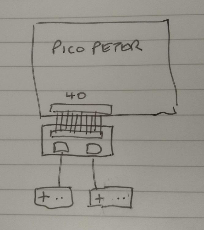 Not to scale Best wishes, Tom Game*Mite, CMM2 Welcome Tape, Creaky old text adventures |
||||
| thwill Guru Joined: 16/09/2019 Location: United KingdomPosts: 3865 |
If you have any experience of the ZX Spectrum then it's analagous to the ZX Interface 2 except the "user port" for the PicoPETER is on the front rather than the back, and it's connected using headers rather than an edge connector of debatable quality. EDIT: and no ROM cartridge slot ... obviously ... so not that much like a ZX Interface 2  Best wishes, Tom Edited 2022-05-01 00:22 by thwill Game*Mite, CMM2 Welcome Tape, Creaky old text adventures |
||||
| Mixtel90 Guru Joined: 05/10/2019 Location: United KingdomPosts: 5770 |
Bill is asking for a "piggy back" pcb that sits inside the case, over the top of Peter's pcb, and stacks on top of the 40-pin sockets in that board (it has 3, one for the Pico and two for expansion boards). The port connectors would be flush with a panel so that joysticks could be plugged in from outside the case. I think that's the idea. For it to work I need to know exactly where those 40-pin connectors are on Peter's board relative to the board edges. Plugging into the 2x20 header is a completely different thing. It might work, but it would probably be rather flimsy. As much a kludge as Sinclair's Interface 2, in fact. lol Mick Zilog Inside! nascom.info for Nascom & Gemini Preliminary MMBasic docs & my PCB designs |
||||
| al18 Senior Member Joined: 06/07/2019 Location: United StatesPosts: 175 |
JLCPCB also finished my boards - built in 2 days. Mine have green solder mask. Their prices are amazing also - 5 boards cost $2.00 and medium speed shipping costs $7.66. It would not be easy to interface two boards together, because of limitations of the PicoMiteVGA. Once you have fully assembled the PicoMiteVGA board, there are only 10 free GPIO pins. The others are dedicated to VGA, Sound, RTC, MicroSD card and PS/2 keyboard. The PicoMiteVGA board is bigger and costs $9.50 to make plus shipping charges. Edited 2022-05-01 00:47 by al18 |
||||
