
|
|
Forum Index : Microcontroller and PC projects : PicoMite: PicoGAME VGA development
| Author | Message | ||||
| Mixtel90 Guru Joined: 05/10/2019 Location: United KingdomPosts: 5731 |
Nope. The normal operation of an ATARI joystick is to pull the lines up to +5 when operated. In fact, on the original PC joystick, I don't think GND is used at all. Analogue inputs are a variable resistor to +5 and all the rest is done on the game card. Mick Zilog Inside! nascom.info for Nascom & Gemini Preliminary MMBasic docs & my PCB designs |
||||
| al18 Senior Member Joined: 06/07/2019 Location: United StatesPosts: 175 |
Request a row of 5 holes spaced at 0.1 inch, so header pins can be connected to an analog joystick. It looks like all of these signals are available on the DB9 connector with 2 paddle inputs Link to the joystick https://components101.com/sites/default/files/component_pin/Joystick-Module-Pinout.png |
||||
| Turbo46 Guru Joined: 24/12/2017 Location: AustraliaPosts: 1593 |
OK, I expect that you are correct for the ATARI but every time a joystick has been used for the Maximites, the switch commons are ground and use a pullup resistor so that zero is the 'on' state. see Bill Keep safe. Live long and prosper. |
||||
| Mixtel90 Guru Joined: 05/10/2019 Location: United KingdomPosts: 5731 |
Sorry, al18, no. You can probably use that, but put it in a box on the end of a wire & plug it into port 2. That has two analogue inputs. This board isn't a controller, it's a sort of console so you'd expect to have controllers with it. :) @Turbo46 Agreed, Bill, but I'm trying to keep the flavour of a "proper" console. I know that microcontroller inputs are almost always active low now, but that's not how they worked historically. I must admit, I've not thought through all the ramifications of using the same socket for both ATARI and NES systems apart from the problems with Trig and the +5 pin. If that would be easier with active low then I might change it. I may have to have another look, but not today. :) Mick Zilog Inside! nascom.info for Nascom & Gemini Preliminary MMBasic docs & my PCB designs |
||||
| al18 Senior Member Joined: 06/07/2019 Location: United StatesPosts: 175 |
Mick, Ok, I'll make a custom cable for the analog joystick port. The signals from Atari paddles would be quite different than the analog joysticks. Atari paddles have a 1 megohm potentiometer, while the joystick has 10k potentiometers for XY. |
||||
| thwill Guru Joined: 16/09/2019 Location: United KingdomPosts: 3846 |
I don't understand how this can work Mick. As you pointed out pin 6 on the NES is 5V whereas on the Atari it is the fire button. EDIT: Hmm, there is a transistor on the PCB in the vicinity, are you doing black magic to allow pin 6 to be switched between power and signal - is that a thing? Note also that the NES is active low. When no buttons are pressed the inputs to the shift register are pulled high - the pull-ups are in the controller itself. Best wishes, Tom Edited 2022-03-21 10:24 by thwill Game*Mite, CMM2 Welcome Tape, Creaky old text adventures |
||||
| Mixtel90 Guru Joined: 05/10/2019 Location: United KingdomPosts: 5731 |
@al18 Joysticks could have two different mechanisms, either a geared system with a 100k pot or a simple system only using part of the track, using a 470k pot. In both cases the output was 0-100k connected from +5. My provisional idea is to use a 10k pull-down on the analogue inputs, giving an input voltage range of 0.3V to 3.3V. If paddles are 1M then I doubt if they'll work. They are only a pot though so I'm not too bothered. Note that none of the joysticks that I've come across actually use a potentiometer wired as such, only as a variable resistor. @thwill It looks like the only positive-going thing is the latch pulse. Active low might be the better option. It also means that I can probably simplify port 2 by simply feeding pin 6 through a 150R resistor from 3V3. The trigger button can pull it down easily (22mA) and it should easily be a low enough value to power the NES controller. The current system does use that transistor. :) GP14 is the Trig input. If GP15 is low then the transistor turns on and pulls pin 6 high to power the NES controller. If GP15 is high then the transistor is off and GP14 reflects the status of pin 6. All controllers will have to work on 3V3 - I haven't got space for level shifting and it makes life difficult. :) In theory the CD4000 series is ok at 3V. Incidentally, I was wrong earlier. I've since found a circuit of a PC game input and the switch-type joystick and buttons are active low. Analogue inputs have a 2k2 series resistor and 10nF cap to ground onto the input of a 558 monostable. Interesting stuff. . Mick Zilog Inside! nascom.info for Nascom & Gemini Preliminary MMBasic docs & my PCB designs |
||||
| Volhout Guru Joined: 05/03/2018 Location: NetherlandsPosts: 3534 |
Why are you trying to keep the board small. Attaching 2 wired joysticks and a VGA cable could use some weight. Otherwise (experience) you put an ashtray or paperweight on it so it does not follow every move you make with the joystick. A bigger box is a pro. PicomiteVGA PETSCII ROBOTS |
||||
| thwill Guru Joined: 16/09/2019 Location: United KingdomPosts: 3846 |
The new old-stock Famicom clone controller that I was playing with previously worked at 3V as did the controller I built on perfboard: 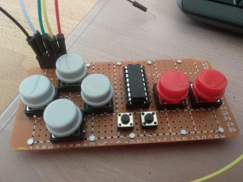 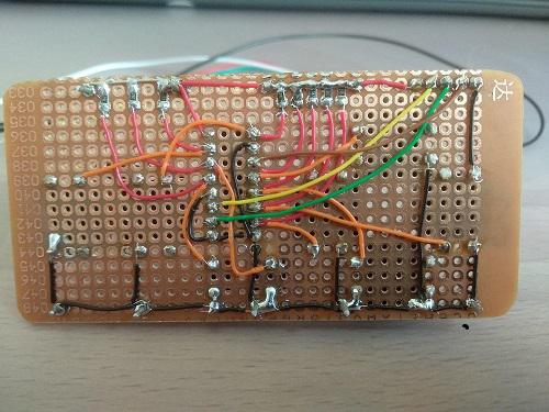 EDIT: The photo of the back of the board is from before @Volhout told me I was pulling down some (unused) pins on the IC that should have been left floating - I've since fixed that, Thanks. Infact in the case of the former it was only when I tried to run it "in-spec" at 5V that I started seeing the problems that ultimately led to me ordering a new cable (not yet fitted after 2 years) and promising to send @Turbo64 the old one so he could teach it to respect its elders. Best wishes, Tom Edited 2022-03-21 21:21 by thwill Game*Mite, CMM2 Welcome Tape, Creaky old text adventures |
||||
| Volhout Guru Joined: 05/03/2018 Location: NetherlandsPosts: 3534 |
The problem may not have been the cable. The controller uses a cmos ic that needs cmos logic levels. These are 0.3xVdd and 0.7xVdd. When the chip is powered from 5V the logic high level minimum is 3.5V. Not compatble wit 3.3V mites. It may have worked, but it also may not have worked. The cmos chip you used, will be happy to run on 3V sot that is the solution.. PicomiteVGA PETSCII ROBOTS |
||||
| thwill Guru Joined: 16/09/2019 Location: United KingdomPosts: 3846 |
Thanks Volhout, I forget the details, but Bill (@Turbo64) and others were advising me on the hardware side and I think we were accounting for that but it's two years ago now so who knows and I don't really want to bother digging through my old posts. EDIT: As I recall in the end we discovered the Famicom controller did work at 5V when connected to the CMM1 by flying leads (10 cm) but not by its cable (2 m) - anyway water under the bridge, no point pursuing this unless I encounter it again with the "Nonetendo VGA PicoMite" - though we probably shouldn't call it that because Nintendo will somehow hear about it (though I fear nobody else will) and issue a Cease & Desist letter. Best wishes, Tom Edited 2022-03-21 21:35 by thwill Game*Mite, CMM2 Welcome Tape, Creaky old text adventures |
||||
| Mixtel90 Guru Joined: 05/10/2019 Location: United KingdomPosts: 5731 |
@Volhout Already pointed out - PCB size stays within cheap rate size at JLCPCB so more accessible. There aren't all that many boxes that are easily available around this size. Both this and the CMM2 box are expensive to buy here because of stupid P&P costs, which really annoy me. I know weight is a problem, but I have the same issue with a CMM2 unless I jam it under my monitor - this is unlikely to be a lot different. :) I bet not many will end up cased anyway. @al18 I've managed to get that joystick module on board. The pull-down resistors for the ADC inputs are now on links so that they can be disconnected, allowing the use of potentiometer inputs. The module is connected to Trig, Paddle-A and Paddle-B of the RH controller socket. @Turbo46 I've now followed the PC input wiring. All switched inputs are active low, analogue inputs are 100k variable resistors from 3V3. @thwill Quality construction, I see. :) Actually, that joystick module and a couple of buttons in a little plastic box would make a rather nice DIY controller. Mick Zilog Inside! nascom.info for Nascom & Gemini Preliminary MMBasic docs & my PCB designs |
||||
| thwill Guru Joined: 16/09/2019 Location: United KingdomPosts: 3846 |
Note the SMD pull-up resistors - I'm learning all the hacks. One day I was going to make that my first PCB, but the harsh mistress of software keeps dragging me back from the loving arms of hardware. Be my guest if you want to run up a PCB, I'm not certain I have a schematic but I can look. It's actually a component of a larger project, the "Nonetendo Lameboy": 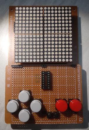 Which was going to use a 28-pin Micromite (back before everything became Pico shaped). The image is just a mockup, though I did get the display wired up and write the MMBasic code to drive it. Best wishes, Tom Game*Mite, CMM2 Welcome Tape, Creaky old text adventures |
||||
| Mixtel90 Guru Joined: 05/10/2019 Location: United KingdomPosts: 5731 |
This is it so far. The joystick module I have has 90 degree connections but this board is designed to have straight connections on the back. Short leads with Duponts could be used. Note that it replaces the RH controller. Component values are in the "should probably work" range. :) I've changed the VGA connector to the one used on the CMM2 as it's easier to get in the UK. 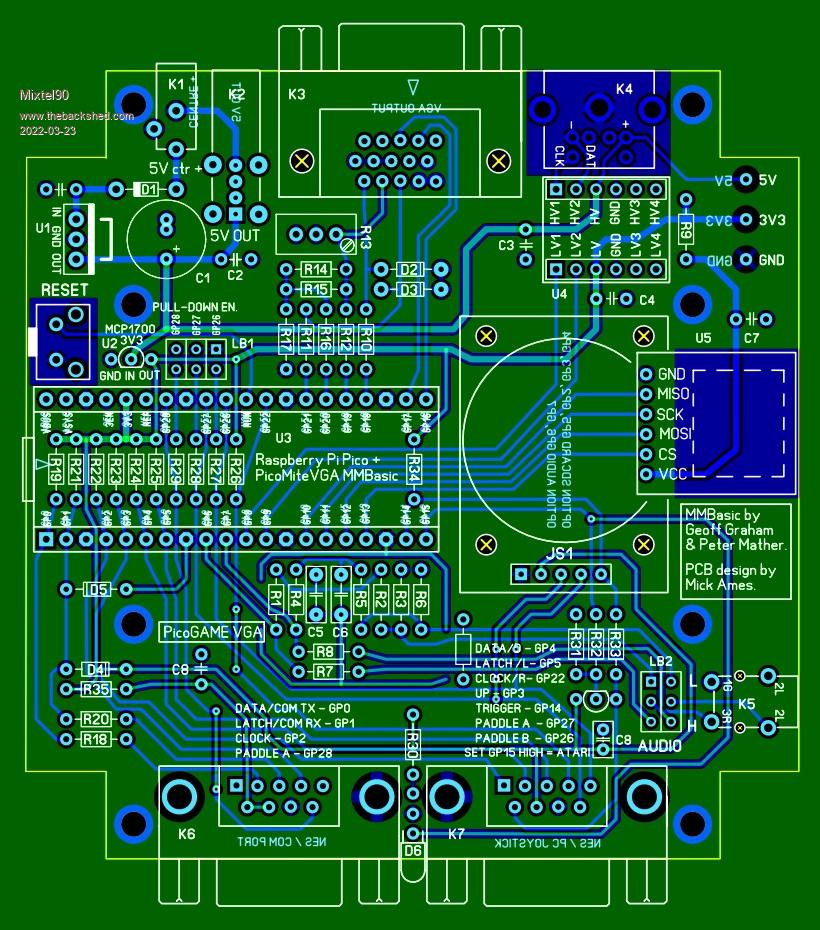 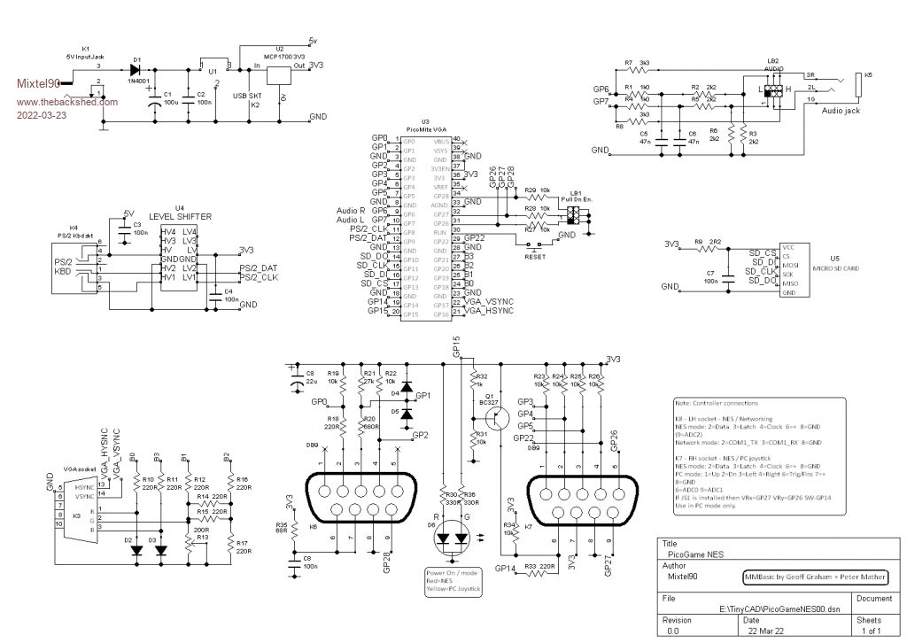 . Mick Zilog Inside! nascom.info for Nascom & Gemini Preliminary MMBasic docs & my PCB designs |
||||
| Volhout Guru Joined: 05/03/2018 Location: NetherlandsPosts: 3534 |
Nice Mick, 1/ Do you really need a 10 turn potmeter to adjust precisely for R13 ? I haven't build a VGA picomite yet, so maybe you do to achieve the correct white balance in 320x240 mode? 2/ Replace D1 with a shottky diode (SB140 or so), otherwise the 5V from the power supply may only be 4.3V or even lower. Keyboards can be power hungry... Regards, Volhout Edited 2022-03-23 01:53 by Volhout PicomiteVGA PETSCII ROBOTS |
||||
| thwill Guru Joined: 16/09/2019 Location: United KingdomPosts: 3846 |
Hi Mick, I vaguely thought there was power-out for a VGA to HDMI converter, can I just not see it, or does it not exist ? Have you checked to see whether any of the components are made of unobtanium ? Was this an academic exercise or are you planning on building one ? If/when you are confident (and have triple checked) and post some Gerbils [sic] then I'm happy to absorb the expense and order the boards and post a couple of them to you along with a pair of controllers ... when they arrive ... June at the earliest. Best wishes, Tom Game*Mite, CMM2 Welcome Tape, Creaky old text adventures |
||||
| Mixtel90 Guru Joined: 05/10/2019 Location: United KingdomPosts: 5731 |
No. In fact, on the one I'm using at present uses the original circuit, with just a 240R resistor in that position (the ladder originally used 120R and 240R values). However, the 10-turn pots are not much different in price to skeleton ones, you don't need to add a series resistor to reduce the range of control (it's only going to be about 150-200R) and they are dustproof. They are just as easy to get from most sources. Mick Zilog Inside! nascom.info for Nascom & Gemini Preliminary MMBasic docs & my PCB designs |
||||
| Volhout Guru Joined: 05/03/2018 Location: NetherlandsPosts: 3534 |
Tom, you may be able to use the USB-A connector for that when you power from the other connector. VGA-HDMI convertors however draw few 100 mA. Not sure how this performs in practise. PicomiteVGA PETSCII ROBOTS |
||||
| Mixtel90 Guru Joined: 05/10/2019 Location: United KingdomPosts: 5731 |
That USB-A is, in fact, the 5V output. :) It's fed from the 5V supply. Normally that's from the input socket with U1 linked out. If U1 is fitted it's a 78xx-compatible switching reg that can handle up to 40V input. It's rated for 800mA continuous or 1A short term current. It should be ok for the total load including a VGA-HDMI converter. As far as I can tell all the components should be ok to get. I've not done a BOM at the moment though. I did it as an exercise to see if I could do it, originally. :) However, I think it checks out ok now. I'll go over it again as I made a couple of minor changes - you can end up with daft things like isolate ground connections sometimes! I think it would be a fun little project. It's still a PicoMite VGA with SDcard and audio, just some specialised IO stuck on it. Mick Zilog Inside! nascom.info for Nascom & Gemini Preliminary MMBasic docs & my PCB designs |
||||
| thwill Guru Joined: 16/09/2019 Location: United KingdomPosts: 3846 |
Thanks Mick, What's with the weird joystick stuck on top ? Is the intent that you hold the entire cased PCB and use it as if it were a large controller ? Best wishes, Tom Game*Mite, CMM2 Welcome Tape, Creaky old text adventures |
||||
