
|
|
Forum Index : Microcontroller and PC projects : Resistor values on PicoMiteVGA board different from PicoMite manual
| Author | Message | ||||
| al18 Senior Member Joined: 06/07/2019 Location: United StatesPosts: 238 |
Page 29 of the PicoMite manual shows the audio circuit made of (2) 1K resistors, (4) 2.2K resistors and (2) 47 nF capacitors. The PicoMiteVGA BOM has changed the resistors to (4) 1K resistors, (2) 4.7K resistors and (2) 47 nF capacitors. The schematics for both are otherwise identical. Why was the change made? The reason I'm asking is because the volume coming out of small earbud headphones is fairly low. Is this circuit meant to drive headphones directly, or should the audio be amplified thru powered speakers? My last comment is I am currently using 47 nF ceramic capacitors on the board because that's all I had at the time. I recently bought some 47 nF MLCC capacitors. Would the MLCC caps improve the volume? Edited 2022-03-29 05:24 by al18 |
||||
| Mixtel90 Guru Joined: 05/10/2019 Location: United KingdomPosts: 8911 |
You'll not get a high output into headphones. Try connecting them to the audio pins via 1k resistors (nothing else needed). You can play with the value but don't go below about 680R to give protection to the PicoMite output. The values shown give a lower output for the PicoMite VGA. TBH I thought they were intended to be the same (approx 1V p-p), but maybe not. They are intended to feed an external amplifier. The type of capacitor won't change the sound to any noticeable extent - and not the volume. Edited 2022-03-29 06:57 by Mixtel90 Mick Zilog Inside! nascom.info for Nascom & Gemini Preliminary MMBasic docs & my PCB designs |
||||
| cosmic frog Guru Joined: 09/02/2012 Location: United KingdomPosts: 308 |
I've connected my headphones directly to the pins of the picomite and it's very loud. I later connected a 10k ohm stereo pot to the picomite pins so I could turn down the headphones to a more acceptable level. Sounds great. Dave. |
||||
| Mixtel90 Guru Joined: 05/10/2019 Location: United KingdomPosts: 8911 |
be careful - the headphones are low resistance and the PicoMite has a very limited maximum output current. That's why I said 680R minimum. Additionally, you are putting DC through the headphones which isn't a good thing really, but keep it down and you'll get away with it. Mick Zilog Inside! nascom.info for Nascom & Gemini Preliminary MMBasic docs & my PCB designs |
||||
| al18 Senior Member Joined: 06/07/2019 Location: United StatesPosts: 238 |
Thanks for the advice -was hoping to get some feedback from Peter. I understand the caps are there to uncouple the signal, so I don't blow anything. I'll try swapping the caps and running the signal thru powered speakers. |
||||
| Geoffg Guru Joined: 06/06/2011 Location: AustraliaPosts: 3362 |
Please don't take this as criticism, I'm just trying to set the record straight, but I must emphasise that Peter and I and all the other people who help on this forum are just hobbyists - we are not in business or under any obligation to do anything. This is something that could be figured out with basic electrical knowledge and, anyway, others have adequately answered the question. So, Peter's input is not needed. Geoff Geoff Graham - http://geoffg.net |
||||
| cosmic frog Guru Joined: 09/02/2012 Location: United KingdomPosts: 308 |
Thanks for the advice. I'll put a 1k resistor in series just before the 10k pot to be safe. Dave. |
||||
| matherp Guru Joined: 11/12/2012 Location: United KingdomPosts: 11513 |
The caps create a low pass filter, they do not decouple the output. The other resistors form part of the filter and also a voltage divider. Component values are not critical. My board copies: https://geoffg.net/Images/Maximite/SchematicLarge.png Here is the recommended circuit from the RP2040 H/W manual 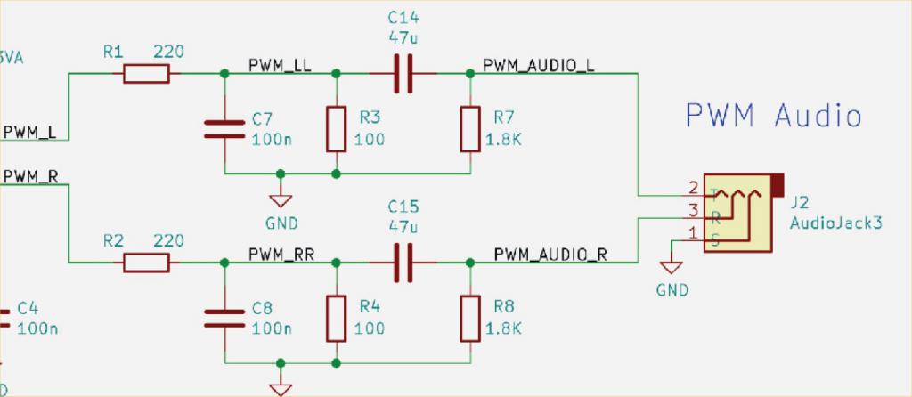 |
||||
| Mixtel90 Guru Joined: 05/10/2019 Location: United KingdomPosts: 8911 |
That's a good circuit in that it takes any DC bias off the output using C14 & C15 (+ end towards R3 and R4 if polarity conscious) and makes sure the caps are discharged using R7 & R8 so there is less of a switch-on pop. Output is set by the ratio of the first two resistors - about 1V. Mick Zilog Inside! nascom.info for Nascom & Gemini Preliminary MMBasic docs & my PCB designs |
||||
| al18 Senior Member Joined: 06/07/2019 Location: United StatesPosts: 238 |
Peter and Mick, Thanks for the very helpful information. Since the PicoMiteVGA board has a 3 pin header for Left, Right and Ground, I'll need to attach the 3.5 mm stereo jack on a small plug-in board. I'm wondering if I should wire a pair of 47 uF to 100 uF caps in series to the outputs. Would it also help if I reduced the 4.7 K resistors to 2.2K resistors and added another pair of 2.2K resistors in series, on the stereo jack board? Edited 2022-03-29 22:25 by al18 |
||||
| Mixtel90 Guru Joined: 05/10/2019 Location: United KingdomPosts: 8911 |
It all depends on what you want to connect the output to. :) For headphones I'd try a 680R upwards resistor and nothing else. The combination of the resistor and the inductance of the headphones will create a filter to smooth out the PWM. If it's too loud then increase the resistor value. For a line output where having DC on the outputs doesn't matter I'd use either of the original or VGA version circuits. For a line output without DC on the output the circuit that Peter has just posted is as good as any. Reducing the 4k7 resistors to 2k2 without making any other changes will just about double the output voltage. The values aren't critical. Put some bits on a breadboard and see which you prefer. :) Mick Zilog Inside! nascom.info for Nascom & Gemini Preliminary MMBasic docs & my PCB designs |
||||
| al18 Senior Member Joined: 06/07/2019 Location: United StatesPosts: 238 |
Swapping the 4.7K resistors for 2.2K has improved the volume thru the headphones. I'm happy  |
||||
| Volhout Guru Joined: 05/03/2018 Location: NetherlandsPosts: 5931 |
Mick, Maybe for your VGA-PWB you can adapt some of the values from the circuit Peter shared. The capacitors C14 and C15 could be mounted where you have the header. PicomiteVGA PETSCII ROBOTS |
||||
| Mixtel90 Guru Joined: 05/10/2019 Location: United KingdomPosts: 8911 |
I'm currently playing with the audio circuit of the VGA mini pcb. :) Mick Zilog Inside! nascom.info for Nascom & Gemini Preliminary MMBasic docs & my PCB designs |
||||
| The Back Shed's forum code is written, and hosted, in Australia. | © JAQ Software 2026 |
