
|
|
Forum Index : Microcontroller and PC projects : 3 channel ARC stimulator
| Author | Message | ||||
| Volhout Guru Joined: 05/03/2018 Location: NetherlandsPosts: 5931 |
My latest (small) project: a 3 channel ARC stimulator. In mains distribution circuit breakers are used to disconnect parts of the grid. When disconnecting a uncontrolled load, these circuit breakers can arc (like a welding arc). Prolonged arcing is destructive. That is why some installations check for the arcing during switching. Generally these installations use optical fiber loops (glass and plastic are superb isolators) without any coating. So external light can pass from the circuit breaker into the fiber, where is is checked by a light detector. The detectors can check the fiber existence by sending a light pulse into one end, and checking the response at the other end, a so called heart beat. To test the detector, this test circuit can be connected to 3 of these fiber loops, and simulate a controlled fiber break, send a controlled light level, and simulate background light entering the system (someone opening a installation cabinet in bright daylight). Since I use a single microcontroller to operate 3 completely independent circuits, the simplest solution was to use a picaxe 20M2 that can do simple multitasking, �and use 7 tasks of the 8 available. Coding this in a picomite is not as straightforward (dangerous to say, I am sure many of you will know how to do it, but I took the simple way out for this project). The code is not optimized, but it simply works. The ARC pulse generated is currently 10ms (1 half cycle at 50Hz) but the software uses the picaxe "pulseout" command, so potentially it can be as fast as 10us. The unit I have to test can handle these short ARC pulses. 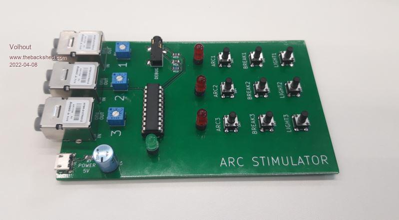 The code (beta-1) '+-----------------------------------------------------------------------------------------+ '| � � � � � � � � � � � � � � � � � � � � � � � � � � � � � � � � � � � � � � � � � � � � | '| ARCGEN � � � � � � � � � � � � � � � � � � � � � � | '| � � � � � � � � � � � � � � � � � � � � � � � � � � � � � � � � � � � � � � � � � � � � | '| � � � � � � � � � 3 channel ARC stimulator with picaxe 20M2 � � � � � � � � � � � � � � | '| Version: V3 � � � � � � � � � � � � � � � � � � � � � � � � � | '| Date: April 8, 2022 Harm de Leeuw (Volhout) � �| '+-----------------------------------------------------------------------------------------+ 'Introduction ----------------------------------------------------------------------------- 'Mains distribution ARC detection systems detect light inrusion in non shielded fiber links 'A heartbeat (light pulse) is used to confirm the existance of fiber link (loop) 'to test these systems in lab environment shielded fibers are used and an intrusion device 'AVAGO HFBR-RLS001Z fibers can be used in combination with AFBR-S10TR001Z optical modules. 'The picaxe controls discrete circuits around the AFBR modules. 'Version control -------------------------------------------------------------------------- 'V1 initial version for board revision 1.0 with keyboard scan, ARC and LIGHT same level 'V2 preliminary version for board revsion 1.1 (added pullup and pulldown resistors 'V3 beta-1 version for board revision 1.1 'Known Bugs ------------------------------------------------------------------------------- 'POWER LED rework to GND. 20M2 pin C.6 cannot be set to output 'chip pinout ------------------------------------------------------------------------------ ' +----U----+ ' +5V � � � � VCC|1 � � �20|VSS GND ' debug � SERIN|2 � � �19|SEROUT debug ' LED3 � � C.7|3 � � �18|B.0 LED1 ' n.u. � � C.6|4 � � �17|B.1 LED2 ' CH1 light � �C.5|5 � � �16|B.2 row0, keyboard ' CH1 ON � � C.4|6 � � �15|B.3 row1, keyboard ' CH2 light � �C.3|7 � � �14|B.4 row2, keyboard ' CH2 ON � � C.2|8 � � �13|B.5 column0, keyboard ' CH3 light � �C.1|9 � � �12|B.6 column1, keyboard ' CH3 ON � � C.0|10 � � 11|B.7 column2, keyboard ' +---------+ #picaxe 20M2 'variables symbol temp=b8 'variable used in key decode symbol key=b9 'decoded key value (0 if no key pressed) symbol old_temp=b10 'backup for temp symbol counter=b11 'timeout counter for false keys symbol cnt1=b12 'blink counter LED 1 symbol cnt2=b13 'blink counter LED 2 symbol cnt3=b14 'blink counter LED 3 symbol Rdirs1=b15 'backup for datadirection symbol Rdirs2=b16 'backup for datadirection 'keyboard input pins symbol R0 = 4 'B.2 symbol R1 = 8 'B.3 symbol R2 = 16 'B.4 symbol RowMask = %00011100 'keyboard output pins symbol C0 = 32 'B.5 symbol C1 = 64 'B.6 symbol C2 = 128 'B.7 'key codes for the 9 keys 'these codes are registered in debug mode, after pressing the resp. key/ symbol ARC3=44 symbol ARC2=52 symbol ARC1=56 symbol BREAK3=76 symbol BREAK2=84 symbol BREAK1=88 symbol LIGHT3=140 symbol LIGHT2=148 symbol LIGHT1=152 '------------------------------------MAIN TASK------------------------------------ start0: 'initialize IO registers dirsB=%11100011 'keyboard columns and LED1,2 output pinsB=%00000011 'keyboard columns low, LED1,2 off dirsC=%10010101 'FET drivers and LED3 output pinsC=%10010101 'FET gates ON, LED3 off 'fill variables key = 0 'this is the main loop. They keys are scanned, and if one is pressed it is decoded 'then the value is passed to "key" which is used in all other tasks to execute a function 'when the task acknowledges the key, it clears the value, and a new key scan can start 'after the key is released get_key_loop: pause 20 'debounce time temp = pinsB and RowMask if �temp=RowMask then goto get_key_loop 'chekc if all row lines high (no key press) pause 20 'debounce time old_temp = temp 'decoding the keys, first column 0 pinsB = pinsB + C0 'make first column high, and debounce pause 10 temp = pinsB and RowMask 'check if all rows high, then a key found if �temp=RowMask then old_temp = old_temp + C0 'add column info to row info in one variable else 'decoding the keys, then column 1 pinsB = pinsB + C1 'make second column high, and debounce pause 10 temp = pinsB and RowMask 'check if all rows high, then a key found if �temp=RowMask then old_temp = old_temp + C1 'add column info to row info in one variable else 'must be column C2, so we do not perform the 3rd test old_temp = old_temp + C2 'add column info to row info in one variable end if end if 'now we clear the column output pins again, to prepare for a key release detection temp = C0 + C1 temp = not temp 'create mask to clear both C0 and C1 pinsB = pinsB & temp pause 10 key = old_temp � 'key now contaisn a unique key number 'debug 'debug can be used to check key values after key press 'when a task clears value "key" we can go on. until then halt here 'we need a time out (200ms) for invalid keys, since these will not be processed counter = 0 get_confirm_key: pause 1 counter = counter+1 if counter = 200 then goto get_release_key if key <> 0 then goto get_confirm_key 'here we wait until all keys are released again get_release_key: pause 20 'debounce time temp = pinsB and RowMask if �temp<>RowMask then goto get_release_key goto get_key_loop '----------------------------------TASK 1 ARC channel 1 -------------------------------- start1: 'ARC and wire break are mutually exclusive (a broken fiber will not pass light) 'therefore these 2 are in one thread if key=ARC1 then 'to generate an accurate ARC pulse use the pulseout command suspend 0 suspend 4 'suspend all tasks that change data direction suspend 5 suspend 6 Rdirs1=dirsC 'backup old data direction pin C.5 Rdirs2=dirsB gosub ON_LED1 pulsout C.5,1000 'puls 1000x10us dirsC=Rdirs1 'restore old data direction dirsB=Rdirs2 resume 0 resume 4 'resume all tasks that change data direction resume 5 resume 6 key=0 'acknowledge key processed pause 300 'keep LED lit for 300ms to make it visible gosub OFF_LED1_PEND else if key=BREAK1 then 'blink the led 5x per second and disable the optical modules for 3 seconds 'that is 15 blink cycles gosub OFF_CH1 key=0 'acknowledge key for cnt1=0 to 15 gosub ON_LED1 pause 100 gosub OFF_LED1 pause 100 next cnt1 gosub ON_CH1 end if end if goto start1 '---------------------------------- TASK2 ARC channel 2 --------------------------------- start2: 'ARC and wire break are mutually exclusive (a broken fiber will not pass light) 'therefore these 2 are in one thread if key=ARC2 then 'new 10ms pulse (can accurate multiples of 10us) suspend 0 suspend 4 'suspend all tasks that change data direction suspend 5 suspend 6 Rdirs1=dirsC 'backup old data direction pin C.5 Rdirs2=dirsB gosub ON_LED2 pulsout C.3,1000 'puls 1000x10us dirsC=Rdirs1 'restore old data direction dirsB=Rdirs2 resume 0 resume 4 'resume all tasks that change data direction resume 5 resume 6 key=0 'acknowledge key pause 300 'keep LED lit for 300ms for visibility gosub OFF_LED2_PEND else if key=BREAK2 then 'blink the led 5x per second and disable the optical modules for 3 seconds 'that is 15 blink cycles gosub OFF_CH2 key=0 'acknowledge key for cnt2=0 to 15 gosub ON_LED2 pause 100 gosub OFF_LED2 pause 100 next cnt2 gosub ON_CH2 end if end if goto start2 '---------------------------------- TASK3 ARC channel 3 --------------------------------- start3: 'ARC and wire break are mutually exclusive (a broken fiber will not pass light) 'therefore these 2 are in one thread if key=ARC3 then 'new 10ms pulse (can accurate multiples of 10us) suspend 0 suspend 4 'suspend all tasks that change data direction suspend 5 suspend 6 Rdirs1=dirsC 'backup old data direction pin C.5 Rdirs2=dirsB gosub ON_LED3 pulsout C.1,1000 'puls 1000x10us dirsC=Rdirs1 'restore old data direction dirsB=Rdirs2 resume 0 resume 4 'resume all tasks that change data direction resume 5 resume 6 key=0 'acknowledge key pause 300 'keep LED lit for 300ms for visibility gosub OFF_LED3_PEND else if key=BREAK3 then 'blink the led 5x per second and disable the optical modules for 3 seconds 'that is 15 blink cycles gosub OFF_CH3 key=0 'acknowledge key for cnt3=0 to 15 gosub ON_LED3 pause 100 gosub OFF_LED3 pause 100 next cnt3 gosub ON_CH3 end if end if goto start3 '---------------------------------- TASK4 light channel 1 --------------------------------- start4: 'continuous light is generated by tristating the 20M2 pin and use the external 'pullup resistor to feet a minute amount of current 'similar a external pulldown resistor can light the keyboard LED at low intensity 'this taks change the data direction of the 20M2 IO pins if key=LIGHT1 then gosub DIM_LED1 gosub DIM_ARC1 key = 0 'acknowledge key pause 7000 gosub OFF_ARC1 gosub OFF_LED1 end if goto start4 '---------------------------------- TASK5 light channel 2 --------------------------------- start5: 'continuous light is generated by tristating the 20M2 pin and use the external 'pullup resistor to feet a minute amount of current 'similar a external pulldown resistor can light the keyboard LED at low intensity 'this taks change the data direction of the 20M2 IO pins if key=LIGHT2 then gosub DIM_LED2 gosub DIM_ARC2 key = 0 pause 7000 gosub OFF_ARC2 gosub OFF_LED2 end if goto start5 '---------------------------------- TASK6 light channel 3 --------------------------------- start6: 'continuous light is generated by tristating the 20M2 pin and use the external 'pullup resistor to feet a minute amount of current 'similar a external pulldown resistor can light the keyboard LED at low intensity 'this taks change the data direction of the 20M2 IO pins if key=LIGHT3 then gosub DIM_LED3 gosub DIM_ARC3 key = 0 pause 7000 gosub OFF_ARC3 gosub OFF_LED3 end if goto start6 '------------------------------ subroutines LED (isolate HW from SW) ----------------------- ON_LED1: low B.0 return DIM_LED1: dirsB = dirsB and 0xFE return OFF_LED1: high B.0 return OFF_LED1_PEND: pinsB = pinsB or 0x01 return ON_LED2: low B.1 return DIM_LED2: dirsB = dirsB and 0xFD return OFF_LED2: high B.1 return OFF_LED2_PEND: pinsB = pinsB or 0x02 return ON_LED3: low C.7 return DIM_LED3: dirsC = dirsC and 0x7F return OFF_LED3: high C.7 return OFF_LED3_PEND: pinsC = pinsC or 0x80 return '--------------------------subroutines CHANNEL (isolate HW from SW) -------------------------- ON_CH1: high C.4 return OFF_CH1: low C.4 return ON_CH2: high C.2 return OFF_CH2: low C.2 return ON_CH3: high C.0 return OFF_CH3: low C.0 return '---------------------------- subroutines ARC (isolate HW from SW) -------------------------- ON_ARC1: high C.5 return DIM_ARC1: dirsC = dirsC and 0xDF return OFF_ARC1: low C.5 return ON_ARC2: high C.3 return DIM_ARC2: dirsC = dirsC and 0xF7 return OFF_ARC2: low C.3 return ON_ARC3: high C.1 return DIM_ARC3: dirsC = dirsC and 0xFD return OFF_ARC3: low C.1 return Too bad the indenting is again f*cked up. Edited 2022-04-08 23:08 by Volhout PicomiteVGA PETSCII ROBOTS |
||||
| Mixtel90 Guru Joined: 05/10/2019 Location: United KingdomPosts: 8911 |
A very nice project, Volhout. One I can appreciate, having been involved with switchgear. :) Mick Zilog Inside! nascom.info for Nascom & Gemini Preliminary MMBasic docs & my PCB designs |
||||
| Tinine Guru Joined: 30/03/2016 Location: United KingdomPosts: 1646 |
At first glance, I am wondering why all the gosubs? Yes, the PicoMite would have no problem with this by using a state-machine for each task and passive delays instead of "pause". State machines are easy to debug because the code is sequential. I naively believed that I invented this technique back in my early days of programming  . Many years later, I read an article about "state machine programming"...Hey wait a minute! . Many years later, I read an article about "state machine programming"...Hey wait a minute! This is exactly what I do with my Mites  Craig |
||||
| al18 Senior Member Joined: 06/07/2019 Location: United StatesPosts: 238 |
Nice. I haven�t seen a Picaxe project in years. I�m interested why you choose a Picaxe 20M2 over the 28 pin Micromite. Not trying to start a war - just curious. |
||||
| Volhout Guru Joined: 05/03/2018 Location: NetherlandsPosts: 5931 |
In essence there are 9 functions, in 6 groups. By using 6 tasks , I can write 6 indepenent pieces of code that can operate independently. In example each of the 6 tasks uses a simple pause statement. In picaxe basic these operate completely independent. So I can start a pause 7000 in task4 while a pause 7000 is half way in task 5. They dont have to wait for other pauses to finish. I am sure that can be done in micromite, but not that simple. I asked Geoff if he could add multitasking to MMBasic, but that was very complex. And it would require resources, memory, as well as cpu power. I am typing this on a smartphone, when I get to my pc, I will explain in a bit more text why this multitasking is soo simple. Edited 2022-04-09 08:32 by Volhout PicomiteVGA PETSCII ROBOTS |
||||
| Tinine Guru Joined: 30/03/2016 Location: United KingdomPosts: 1646 |
For tasking on the MX170, I use the ByPic. Up to 20 tasks can be handled and if the program consists of nothing but tasks, the command prompt remains active which enables the user to interrogate variables or whatever. Bypic is also pretty darned quick. I seem to remember that it was 4 or 8 times the speed of my Explore E-100. Scheduling - ByPic.pdf "Traffic light" example Craig Edited 2022-04-09 10:14 by Tinine |
||||
| Mixtel90 Guru Joined: 05/10/2019 Location: United KingdomPosts: 8911 |
You could probably use TIMER as a form of multitasking. Compare it with a value that you've previously calculated for the start of a task. If greater or equal to then run the task and calculate the next compare value. No good if you want your program to run for over 200 million years though. :( Mick Zilog Inside! nascom.info for Nascom & Gemini Preliminary MMBasic docs & my PCB designs |
||||
| Tinine Guru Joined: 30/03/2016 Location: United KingdomPosts: 1646 |
The pesky 64bit limitation; gets me every time Craig |
||||
| JohnS Guru Joined: 18/11/2011 Location: United KingdomPosts: 4335 |
"I plan to live forever - or die trying." John |
||||
| Volhout Guru Joined: 05/03/2018 Location: NetherlandsPosts: 5931 |
Hi Al18, Let me try to explain the benefit of multitasking in development of simple code. In my application I have a keyboard scan (task0) that scans a matrix of keys, and delivers a key value in a global variable. Each of the other tasks wait's until if recognises it's assigned key, acknowledges it, and then executes a function that is related to that key value. By this architecture, each of the functions can be executed simultaneously. Press key 1, task 1 recognises the key, acknowledges it, and executes the function. Even if this function lasts 1 minute, key scan routine will deliver a new key function when I press the second key, and task 2 (or 3 or 4) recognises the key and starts executing. So the keys drive virtually independed functions. Technically this is also possible in a single tasking environment, but then you need some kind of sequencer that can start and stop individual functions based on timer values. There are some restrictions to the multitasking in the pickaxe 20M2 pickaxe (as for any multitasking system) - avoid shared resources (the tasks cannot independently change the same GPIO pin, or use the same I2C bus, unless special precautions are taken - the 20M2 uses hard scheduling of the tasks, and to minimise the impact that has on the performance, they change the CPU clock in multitasking. When a standard pickaxe runs at 4MHz, in multitasking it runs at 32MHz (8 tasks, 4 MHz each). Not all microcontrollers can do that (a 125MHz pico mite would have to run at 1GHz). - the pickaxe only uses global variables in basic (the interpreter will have 8 individual stacks, but the user is unaware) to avoid explosive memory use. For this small ARC test system this was no limitation. And actually, I also used 4 tasks in an earlier project: an alarm clock that was based on a pickaxe 18M2. I actually like programming in multiple tasks, since I can focus on the algorithms that are needed to do the ask, and not worry about the interaction between them. The interaction is often more complicated to deal with than the actual algorithm. Geoff and Peter already have implemented some function in MMBasic in the background, that is also a form of multitasking. Only in these cases specific to a function or command. Some examples are: - serial ports: you write to a buffer, and in the background these are send to the serial port - ADC command: You give it the command to gather X samples at Y speed, and get a message when it is done And there will be others, mostly hardware related, that give authority back to the basic interpreter, before the actual work is finalised. Tinine als uses multitasking a lot (the parallax has multiple cores, so that is real multitasking...) I hope this explains my choice for the 20M2 Regards, Volhout Edited 2022-04-10 00:19 by Volhout PicomiteVGA PETSCII ROBOTS |
||||
| Volhout Guru Joined: 05/03/2018 Location: NetherlandsPosts: 5931 |
This is my limited knowledge of the pickaxe basic language. I wanted an abstraction layer between hardware and software. Something that translates LED_ON to a certain GPIO. The way I know to do that was either macro's or subroutines. In the final version, using the 20M2 it happens that all subroutines ended up being single commands, so it would have been more compact to work with #define's or symbols. But an earlier version running on a different chip had some subroutines that existed of multiple lines. I may still do this change for the final version Volhout Edited 2022-04-10 00:29 by Volhout PicomiteVGA PETSCII ROBOTS |
||||
| al18 Senior Member Joined: 06/07/2019 Location: United StatesPosts: 238 |
Thanks for the detailed explanation. I was not aware the Picaxe 20M2 could do this type of multitasking. The Picaxe parts don�t get a lot of visibility in the US. |
||||
| lizby Guru Joined: 17/05/2016 Location: United StatesPosts: 3784 |
Really excellent project. It's worth a reminder that this is "multitasking", not "multi-threading"--processing time is sliced--there are not multiple cores. This allows some neat simplifications, as Volhout has shown, but some multi-tasking problems are better handled in a single task. PicoMite, Armmite F4, SensorKits, MMBasic Hardware, Games, etc. on FOTS |
||||
| Tinine Guru Joined: 30/03/2016 Location: United KingdomPosts: 1646 |
Only approximated Volhout's code but this is the sort of state-machine tasking that I use. DIM INTEGER true = -1, false = 0 dim integer task1_active = true, task2_active = true, task3_active = true dim integer task4_active = true, task5_active = true, task6_active = true, task7_active = true dim integer t1_prog_cntr = 1, t2_prog_cntr = 1, t3_prog_cntr = 1, t4_prog_cntr = 1 dim integer t5_prog_cntr = 1, t6_prog_cntr = 1, t7_prog_cntr = 1 dim integer t1_pause = 0, t2_pause = 0, t3_pause = 0, t4_pause = 0, t5_pause = 0, t6_pause = 0, t7_pause = 0 dim integer t1_cntr = 0, t2_cntr = 0, t3_cntr = 0, t4_cntr = 0, t5_cntr = 0, t6_cntr = 0, t7_cntr = 0 do '=============================Insert priority code here ' Start/Stop signal, etc.? '============================= if task1_active then select case t1_prog_cntr case 1 'if key=ARC1 then 'to generate an accurate ARC pulse use the pulseout command 'suspend 0 'suspend 4 'suspend all tasks that change data direction 'suspend 5 'suspend 6 if var_key = ARC1 then task2_active = false task3_active = false task4_active = false t1_prog_cntr = t1_prog_cntr + 1 'exit this step to deactivate other tasks else t1_prog_cntr = 4 'Check for var_key = BREAK end if case 2 Rdirs1=dirsC 'backup old data direction pin C.5 Rdirs2=dirsB gosub ON_LED1 'Gosub is unnecessary overhead pulsout C.5,1000 'puls 1000x10us dirsC=Rdirs1 'restore old data direction dirsB=Rdirs2 task2_active = true task3_active = true task4_active = true var_key = 0 t1_pause = timer + 300 t1_prog_cntr = t1_prog_cntr + 1 case 3 if timer => t1_pause then gosub OFF_LED1_PEND 'Gosub is unnecessary overhead t1_prog_cntr = 1 'Back to start end if case 4 if var_key = BREAK1 then 'blink the led 5x per second and disable the optical modules for 3 seconds 'that is 15 blink cycles gosub OFF_CH1 'Gosub is unnecessary overhead var_key=0 'acknowledge key t1_cntr = 0 t1_prog_cntr = t1_prog_cntr + 1 else t1_prog_cntr = 1 'Back to start end if case 5 gosub ON_LED1 'Gosub is unnecessary overhead t1_pause = timer + 100 t1_prog_cntr = t1_prog_cntr + 1 case 6 if timer => t1_pause then gosub OFF_LED1 'Gosub is unnecessary overhead t1_pause = timer + 100 t1_prog_cntr = t1_prog_cntr + 1 end if case 7 if timer => t1_pause then t1_cntr = t1_cntr + 1 if t1_cntr = 15 then gosub ON_CH1 'Gosub is unnecessary overhead t1_prog_cntr = 1 'we're done so back to beginning else t1_prog_cntr = 5 'not done flashing yet end if end if case else end select end if if task2_active then select case t2_prog_cntr case 1 case 2 case 3 case 4 end select end if if task3_active then select case t3_prog_cntr case 1 case 2 case 3 case 4 end select end if if task4_active then select case t4_prog_cntr case 1 case 2 case 3 case 4 end select end if if task5_active then select case t5_prog_cntr case 1 case 2 case 3 case 4 end select end if if task6_active then select case t6_prog_cntr case 1 case 2 case 3 case 4 end select end if if task7_active then select case t7_prog_cntr case 1 case 2 case 3 case 4 end select end if loop Craig |
||||
| Volhout Guru Joined: 05/03/2018 Location: NetherlandsPosts: 5931 |
Thanks Tinine, I will try this scheduler for a next project. As I said, I like using multitasking, so I will play with it and see what it can do for me. The PICAXE is very limited in it's application field, so I can only use it in few cases. Appreciate the effort you took to massage the scheduler around my code. Regards, Volhout. PicomiteVGA PETSCII ROBOTS |
||||
| Tinine Guru Joined: 30/03/2016 Location: United KingdomPosts: 1646 |
No problem I have been using this method for years and it is really snappy.You have probably already realised that the task-disabling isn't even necessary for your application because everything is sequential so no chance of a conflict. Craig |
||||
| Volhout Guru Joined: 05/03/2018 Location: NetherlandsPosts: 5931 |
Hi Craig, In the picaxe code the task disabling is needed. There is a chance of 10 in 7000 that during the ARC pulse, the background light period terminates and the IO pin is set to pushpull. When the ARC task restores the data direction, it will put it back to input mode. To understand how this works: Ther is a LED with 3k resistor to the IO pin. And a 12k pullup from the IO pin to +5v. When the pin is diven high, 1mA through the LED. When set to input, 200uA through the LED, when set low, LED is off. That is where the data direction comes into play. I currently disable tasks 4, 5 and 6 everywhere. But I could limit that to stop task 4 from task 1, stop task 5 from task2 and stop task6 from task 3. Edited 2022-04-12 07:40 by Volhout PicomiteVGA PETSCII ROBOTS |
||||
TassyJim Guru Joined: 07/08/2011 Location: AustraliaPosts: 6538 |
I remember playing with arc shutes in my training days. In my working days, arcs when switching 229kV at night are impressive but the ones that I didn't like were manually pulling links on 415V and 200-300 amps load. You learnt to be quick. Jim VK7JH MMedit |
||||
| Tinine Guru Joined: 30/03/2016 Location: United KingdomPosts: 1646 |
Ah, slight misunderstanding. I realise that this is the case with the picaxe tasks because they can be anywhere at any time. No, I was referring to the state-machine method where everything is sequential. The critical stuff can all happen in the same scan whilst the other tasks are waiting for processor time. Craig |
||||
| The Back Shed's forum code is written, and hosted, in Australia. | © JAQ Software 2026 |
