
|
|
Forum Index : Microcontroller and PC projects : Help how to hookup HC-SR04
| Author | Message | ||||
| Rickard5 Guru Joined: 31/03/2022 Location: United StatesPosts: 463 |
Hello everybody I'm trying to figure out how to hookup the HC-SR04 o the Picomite and the only info I found was from the manual : my question is, so how do I build this Resistor Divider? and what pins do I use ? I may be Vulgar, but , while I'm poor, I'm Industrious, Honest, and trustworthy! I Know my Place |
||||
| Tinine Guru Joined: 30/03/2016 Location: United KingdomPosts: 1646 |
This is from my Android app "Electrodoc" (nice). Play with combinations that suit what you have in stock or whatever power dissipation you want to shoot for. 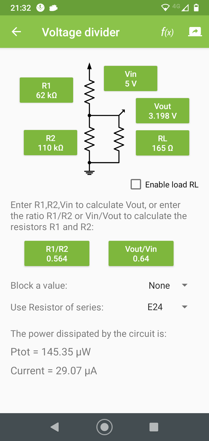 Craig |
||||
| Mixtel90 Guru Joined: 05/10/2019 Location: United KingdomPosts: 8904 |
I doubt if the Pico input will load that with 165R! Try 3.3K on top and 6.8K on the bottom to give 3.366V off-load. The Pico input is pretty high resistance but that is safe and will drop a little further. Mick Zilog Inside! nascom.info for Nascom & Gemini Preliminary MMBasic docs & my PCB designs |
||||
| Rickard5 Guru Joined: 31/03/2022 Location: United StatesPosts: 463 |
so VCC goes Strait to 5v pin GND goes strait to GND pin ECHO goes straight to an input and Trig goes through visitor ladder ? Thanks Guys I feel Dumb but I don't know I may be Vulgar, but , while I'm poor, I'm Industrious, Honest, and trustworthy! I Know my Place |
||||
TassyJim Guru Joined: 07/08/2011 Location: AustraliaPosts: 6538 |
TRIGGER goes straight to an output and ECHO goes through resistor ladder to input VK7JH MMedit |
||||
| Rickard5 Guru Joined: 31/03/2022 Location: United StatesPosts: 463 |
OK Cool Thanks Jim now I just have to go though the unenviable task of sorting though the mega box of Resistors looking for 3.3 K and 6.8k resistors :)2 then I'm off to try it :) I may be Vulgar, but , while I'm poor, I'm Industrious, Honest, and trustworthy! I Know my Place |
||||
| phil99 Guru Joined: 11/02/2018 Location: AustraliaPosts: 3289 |
Getting the exact resistors isn't very important. Just make the bottom one twice the value (or a little less to be safe) of the top one. Other examples:- 5.1k, 10k 12k, 22k 2.7k, 5.1k The required voltage ratio is 3.3 / 5 = 2/3 So you can use any three of the same value in series to get an exact division of 2/3. |
||||
| KD5ZXG Regular Member Joined: 21/01/2022 Location: United StatesPosts: 53 |
Cut 5V simply in half works fine too. Anything over 2V is probably logic true. You can hit anywhere from there to 3.3V. Edited 2022-04-18 12:39 by KD5ZXG |
||||
| Mixtel90 Guru Joined: 05/10/2019 Location: United KingdomPosts: 8904 |
Using 50% is borderline and there's no real need to do it. It increases problems due to noise on the signal and supply lines. e.g. you have a Pico input that happens to need 2.1v (within spec). If you use 50% then you have to guarantee an output of 4.2V. If your "5V" rail is at 4.7V then that may not be possible. Also, don't use too high a value if using a potential divider for level shifting into MOS logic. Inputs have a high impedance and capacitance so high resistor values will slow the logic down. That can lead to all sorts of interesting bugs to find. :) You generally have plenty of current to spare so use it. Why use a 10uA divider when you can use a 1mA one? Mick Zilog Inside! nascom.info for Nascom & Gemini Preliminary MMBasic docs & my PCB designs |
||||
| The Back Shed's forum code is written, and hosted, in Australia. | © JAQ Software 2026 |
