
|
|
Forum Index : Electronics : Choke rules of thumb?
| Author | Message | ||||
| poida Guru Joined: 02/02/2017 Location: AustraliaPosts: 1389 |
The low side and high side Gate drive for the 50Hz squarewave (fundamental) are pins 3 and 6 respectively. from the EG002 pdf: 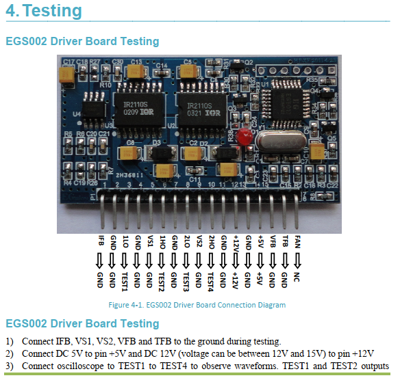  wronger than a phone book full of wrong phone numbers |
||||
| Godoh Guru Joined: 26/09/2020 Location: AustraliaPosts: 379 |
The data sheets I have for the Sunyima boards show the choke connected to the output terminal of the board at the terminal nearest to the 8010 board. The other transformer terminal is connected to the furthest terminal from the board here is a pdf. Pete SUNYIMA inverter board.pdf |
||||
Haxby Guru Joined: 07/07/2008 Location: AustraliaPosts: 419 |
Either way, you'd have to check with an oscilloscope. There's no telling what they know and don't know. And different versions are released frequently. |
||||
| Haxby Guru Joined: 07/07/2008 Location: AustraliaPosts: 419 |
Somewhere in this forum, someone suggested a brilliant idea: one choke per MOSFET half bridge, with multiple chokes on one side of the transformer. This eliminates the issue of having to turn on multiple paralleled MOSFETs together at exactly the same time. I've looked but can't find the original thread. It might have been Mark or Klaus. 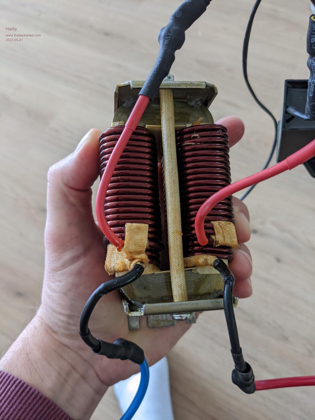 I'm wanting to experiment with this idea. I have an aerosharp choke that is labelled 3mH, 20A, and has two separate windings. I ASSUME that means each winding can handle 20A and each winding is 1.5mH. (is that right?) If I drive each winding simultaneously with matching half bridges, will the single choke act as two separate chokes? I'm thinking if so, I won't have to unwind it. I could just make the gap a bit bigger to decrease the inductance. |
||||
| Solar Mike Guru Joined: 08/02/2015 Location: New ZealandPosts: 1125 |
There was some discussion about this here.Multiple Chokes scroll down near the bottom of the page. Edit: Any value near or greater than 200uH will work, eg at 23kH Modulation 200uH = 29R impedance, while 50 Hz = 0.06R, thus giving good isolation between the pwm frequency and the 50Hz going into your power transformer. ultimately you want as big a cross section wire to support your primary current and enough turns to get as much inductance as you can without the core saturating. Cheers Mike Edited 2022-05-01 15:44 by Solar Mike |
||||
| wiseguy Guru Joined: 21/06/2018 Location: AustraliaPosts: 1000 |
Keep in mind turning on an inductive load with paralleled MOSFETS may not be as bad as it first sounds. �In theory consider an inductor connected to an emf at time zero. The current will ramp up from zero to some maximum (hopefully before saturation) before the FETs turn off again. �So a fast turning on FET does not shoulder full current before the others switch on to share the ramping current. It is switching off that is a bigger issue as the last FET to turn off is shouldering all the highest current at that instant. I design for fastest possible turn on and turn off of FETs to minimise these issues and separate chokes should also help. Smaller chokes are more friendly to wind and have less mechanical issues to mount too. FYI I am also about to experiment with the EGS002 module by adding some gating to create drives for my inverse opto driven power stages, I am curious to see how it will perform. I was thinking more about the choke on the HF Power drive to the transformer. It would not hurt to have 10nF or larger capacitor to ground at the node of the choke and transformer. The current here is mostly 50Hz due to the chokes HF integration effect and the capacitor would help stop (minimise) any HF noise from entering the toroid and being coupled to the mains windings. �The suggested capacitor would have essentially no effect to the 50Hz. Edited 2022-05-01 15:49 by wiseguy If at first you dont succeed, I suggest you avoid sky diving.... Cheers Mike |
||||
| Solar Mike Guru Joined: 08/02/2015 Location: New ZealandPosts: 1125 |
Great Idea, may dissipate a little reactive power, so a couple of > 100v polypropylene types say 0,01 and 0.001uf paralleled for best performance. Cheers Mike |
||||
| Haxby Guru Joined: 07/07/2008 Location: AustraliaPosts: 419 |
You'd think all this would be easy but the more you look into it the harder it gets. This video shows what happens on fast turnoff of the IGBT when switching a relatively small inductor. A giant spike many times the input voltage. This will happen during the dead time before the other IGBT has a chance to clamp it. The suggestion in the video is to add capacitance right at the IGBT. Thoughts on this? By the way I'm still playing with the spdif parts as optocouplers for my designs. If you need to inverse the logic of the EG8010, you can try to pry leg number 9 off the PCB and connect to 5v. This will invert all outputs. |
||||
| Haxby Guru Joined: 07/07/2008 Location: AustraliaPosts: 419 |
Very good ideas! Thanks gents! |
||||
| wiseguy Guru Joined: 21/06/2018 Location: AustraliaPosts: 1000 |
Haxby can I clarify what you are doing. Are you using an H bridge with the intention of using IGBT's. Is your concern related to spikes in between upper and lower FETs switching ? IGBts used in a bridge are quite different to what the chap on youtube is doing. He has a single IGBT and an inductor on the collector - guaranteed to give huge spikes at switch off. When you have an H bridge of FETs or IGBT's the diodes in them form a very fast acting bridge rectifier as far as inductive energy is concerned and the energy is returned to the bus / filter capacitor. The spike level will be a function of the circuit layout, with short solid wiring it will be quite small. If you use a CRO and are not happy with the results try using some fast switching power diodes such as BYV32-200 or MUR420 or APT30D20 or similar across the device - I see maybe a few volts above the supply rail due to inductive energy in my inverter. If at first you dont succeed, I suggest you avoid sky diving.... Cheers Mike |
||||
| Haxby Guru Joined: 07/07/2008 Location: AustraliaPosts: 419 |
I'm not doing anything specific just yet. I'm playing around with an EGS002 and this is my first foray into SPWM style inverters. Chokes are my least understood component in the design so that's why I'm "thinking aloud" in this thread. I had EMI issues in my warpverter build, mostly because I was switching higher voltages. Around 200 to 350v DC. The di/dt in a warpverter build is well managed, as it naturally follows the 50hz sine wave, but the dv/dt (sharp square waves of hundreds of volts) unearthed a lot of gate drive issues that I think I have now tamed with using gate drivers with Miller clamp. (UCC5350M) But as I contemplate a 200vDC SPWM inverter design, I think I have to be more careful. I think putting the choke as close to the fast transitions as possible, and a little capacitance after the choke is a good start to minimising EMI. |
||||
| wiseguy Guru Joined: 21/06/2018 Location: AustraliaPosts: 1000 |
Warp and I have had quite a few discussions on chokes over the years and although we use slightly different ways of explaining how they function we have many fundamental agreements. The toroidal transformer needs a capacitor on the mains winding, its primary function is to filter out the HF switching frequency by being a very low impedance to ~20kHz, but a relatively high impedance at 50Hz. If there was no choke the capacitors impedance would be reflected back to the primary and the impedance is further lowered as a function of the turns ratio. If we tried to apply the 20kHz PWM to the primary now directly with no choke, it is essentially trying to drive almost a short circuit at 20kHz, high and tending towards destructive currents will flow in the power FETs. For simplification I will ignore the half of the H bridge that alternately toggles one side of the transformer to 48V or to zero volts and just look at the HF side Now looking at what a half bridge with a series inductor at the centre of the bridge looks like. If the lower FET is replaced with a diode the circuit is identical to a switching regulator power stage including the output inductor - in this case our choke. Lets put the lower FET back in, we still have a switching regulator but now with an active lossless diode (the FET) on the bottom half. If we apply a 50Hz sinewave control signal to our switching regulator we will get out instead of a fixed DC, we get a 50Hz waveform but it can only switch from zero to +maximum we need it to also go from zero to -maximum. This is essentially what the EG8010 does to create its inverter function. The choke has to carry the 50Hz fundamental full current and it does this by ratcheting small but varying chunks of current at a 20kHz switching rate, that is why the inductor should not saturate at full load due to the stress it would place on the HF switches. For the suggested value of ~ 40uH it is not a constant for any given voltage, the choke value is directly related to the applied voltage also. For a 96V supply I would expect the inductor to store the same amount of energy for a given output power but it would be at half the current as the 48V unit and would be closer to 100uH to achieve this. I am unsure whether this explanation will help at all or just adds further headaches to your understanding.... Edited 2022-05-02 00:59 by wiseguy If at first you dont succeed, I suggest you avoid sky diving.... Cheers Mike |
||||
| Haxby Guru Joined: 07/07/2008 Location: AustraliaPosts: 419 |
It helps, thankyou. Put simply, I'm looking for rules of thumb for getting started in experimenting, and your post above has given me another one: The uH of the choke should be similar to the battery voltage: so 50uH for a 50v system, 200uH for a 200v system, etc. And warp once said that the (silicon steel) choke should be about a third the size of the transformer. So with these two rules of thumb, I can find something close to start experimenting with. |
||||
| wiseguy Guru Joined: 21/06/2018 Location: AustraliaPosts: 1000 |
I use a website to help with my modelling and as a starting point and a sanity check when designing transformer and inductances. It is http://schmidt-walter-schaltnetzteile.de/smps_e/smps_e.html If you use the first buck regulator choice and enter the values of Vin min & max, Vout and I out and switching frequency it helps with the inductor design and suggests cores etc to achieve the result, the site is a bit old and doesnt know about newer sendust materials etc but it is a good starting point nevertheless. For the inverter If you select say 44Vmin for a flat battery 54Vmax for a charged battery, then keeping in mind the sinusoidal component for power what is the expected peak/max current, the max instantaneous voltage the transformer can see with 44Vin is say 42V (some losses....) and you have a starting point to play with inductor calculations. Dont forget the DC voltage will only provide 0.707 of the AC transformer RMS voltage which in the above example will be around 30VAC RMS. Also the peak inductor current will be ~1.414 times the average current (at the sine peak) for a given power out. If I have made any incorrect assumptions or if anyone else has similar hints methods etc please post away - it all helps. If at first you dont succeed, I suggest you avoid sky diving.... Cheers Mike |
||||
| Murphy's friend Guru Joined: 04/10/2019 Location: AustraliaPosts: 584 |
These comments got me curious so I took the covers of one of my inverters to see what swapping the mosfet drives over does. Well, absolutely no difference. Nice clean sine wave either way. I should mention that my inverters are Poida's single Nano version (my PCB), modified, as per Wiseguy's suggestion, to isolated totem pole drive. There is a 106uH choke on one side of the primary, this is made from 2 of the larger Aerosharp choke C cores (assembled to make an E core) and wound with 14 turns of 30mm sq wire, 1.2mm air gap. There are proper sealed suppressors at the AC output as well as two clip on ferrite suppressors. So, in my experience, it did not matter what side of the transformer the choke was. |
||||
| Haxby Guru Joined: 07/07/2008 Location: AustraliaPosts: 419 |
The way I see it, to limit the EMI, you want to decrease the square waves in the circuit as soon as possible. Putting the choke on the SPWM side will do this. The inverter will still transmit EMI but at least the antennas in it will be smaller. At the two output inverter terminals, one side switches slowly at 50 hz, pretty much at the zero crossing of the sine wave, so there is little current being switched at this point. So very low dI/dT. And next to no switching losses in the fets. The other output side is switching like crazy, at all points of the output sine wave, all under load, so both dI/dT and dV/dT is high. Since the choke is designed to convert SPWM to more of a sine wave, it would make sense to have it as close to the SPWM side of the half bridge as possible. The less cabling (antennas) carrying the harsh SPWM the better. The transformer has capacitance between primary and secondary winding as well as from both windings to the core, so again in this case you want to limit the SPWM that the transformer sees as much as possible. Either way your output sine wave won't really show what's going on. So might as well pop the choke on the PWM side if it's all the same. |
||||
| Murphy's friend Guru Joined: 04/10/2019 Location: AustraliaPosts: 584 |
I get the gist of what you are suggesting but which is the PWM side with Poida's Nano output? There are two drive signals coming from it and on my 30yo CRO their output looks the same. I'll try a transistor radio close to the inverter, to see if there is radio interference but I doubt it. It really does not matter to me what is going on inside the earthed metal case of the inverter as long as any high frequency noise stays in there. |
||||
| wiseguy Guru Joined: 21/06/2018 Location: AustraliaPosts: 1000 |
On my 1 year old CRO they look the same to me too  For the first 180 degrees one half of the bridge is PWM whilst the other side is ground. For the first 180 degrees one half of the bridge is PWM whilst the other side is ground.Then for the next 180 degrees they swap around, so the answer to which side is PWM - the answer is both with a 50% sharing arrangement. I decided to use 2 chokes - Haxbys thinking - get rid of the squarewaves asap. My solution was to put two windings on a toroidal choke, series aiding, with the transformer between the other end of the windings as here top sketch. I havent used an AM radio anywhere near it - I was worried the radio might explode..... I am almost finished designing another control PCB at the moment, using the EG8010 but with some gating driving the 50% PWM duty cycle with inverse optos per side. Essentially it will drive the 50% sharing arrangement as per the Nano, I am curious how well it will work. Edited 2022-05-10 01:12 by wiseguy If at first you dont succeed, I suggest you avoid sky diving.... Cheers Mike |
||||
| Haxby Guru Joined: 07/07/2008 Location: AustraliaPosts: 419 |
I don't have the nano board. My sunyima board follows the EGS002 recommended schematic that has the SPWM on one side only. Modifying the code of the nano could be considered to get the SPWM on one side. I think there is merit in having a choke on each side no matter how the output terminals are driven. If you imagine that the transformer is a capacitor as well, then even the 50hz side, switching at the zero crossing of the output waveform, will still have to charge/discharge the (hopefully small) capacitance in the transformer. So my statement earlier that the 50hz side doesn't have to switch any current may not be entirely accurate. Maybe the optimum solution is to have a large choke on the SPWM side and a smaller choke on the 50hz side. It might sound like a bit of a storm in a teacup, but I'll be playing with 200vdc input voltages, so all these pesky EMI and capacitance effects get amplified. |
||||
| Murphy's friend Guru Joined: 04/10/2019 Location: AustraliaPosts: 584 |
Well, with 200VDC there would be a much bigger problem than with my 56VDC. I suppose you knew what you were in fore when playing with such high DC voltages  . .I did the transistor radio test today, yes, there is a faint crackle/ hum from the speaker, audible on top of the tuned station program, it disappears when the inverter is off. BUT, the radio was sitting on top of the inverter, not at its usual place on the window sill. No interference up there  . .I still need to be convinced about that transformer capacitance to the core. A capacitor has two terminals, there is none connected to the core, its fully floating electrically. Good to know that Poida's Nano performs better  than that pesky EG002 board interference wise . I have given up on these Chinese boards very early on with my inverter building experiments. Initially we built our own control boards with the IR2110 Hi and Lo side drivers but then Poida's nano came along and I have not looked back since. than that pesky EG002 board interference wise . I have given up on these Chinese boards very early on with my inverter building experiments. Initially we built our own control boards with the IR2110 Hi and Lo side drivers but then Poida's nano came along and I have not looked back since.Certainly no more un explained inverter failures. |
||||
