
|
|
Forum Index : Microcontroller and PC projects : Shall I call this one Gemini?
| Author | Message | ||||
| Mixtel90 Guru Joined: 05/10/2019 Location: United KingdomPosts: 5737 |
Pico 1 has a problem in that it's designed to be powered from the regulator only. You'll have to attack the PCB and cut the connection to the 3EN pin (37). It's on the bottom and shouldn't be too bad to get to with a knife. Leave H1 and H2 off to isolate Pico 2. You don't want the regulator involved. That makes sense: Pico 1 VBUS can power Pico 2 VSYS. Shouldn't cause a problem. You only have console access to Pico 1. You may even be ok powering both from separate USB ports as they are diode isolated from each other on the Picos. You might be able to have a terminal session for each then and *really* confuse yourself. :) You may have to leave off any serial links while flashing firmware at any time. We don't know what the pins are doing until the firmware is in and in control. Edit: Ah, you found it. :) Edited 2022-08-09 04:20 by Mixtel90 Mick Zilog Inside! nascom.info for Nascom & Gemini Preliminary MMBasic docs & my PCB designs |
||||
| Rickard5 Guru Joined: 31/03/2022 Location: United StatesPosts: 328 |
Hi Mick and Everyone else, can I be so bold as to as if there is any sample code yet on how to pass data back and forth between Pico 1 and Pico 2 ? My Ideal situation right now is how can I use Pico 1 as my master control processor and Display then offload all of the GPIO to Pico 2, and while I know there are no interrupts in MMBasic, Ideally in an any and all loops on Pico 2, I'd be able to check specific GPIO Pins for like Limit switches and on high shut everything on Pico2 down for Safety. also something I'd love to do is to record all I/O Data to a Raspberry Pi, so I can import it to a spreadsheet and work with all the data logged from pico2. I'm sorry if my thoughts come out as word Salad, but I'm no Programmer and right now the Pear has me so excited, sitting here looking at it's potential I hope to Realize THE Pico Pear wins the first Prize for Solution in search of a problem :) I turned the volume on the monitor to max and could hear sound. Thanks Stanleyella |
||||
TassyJim Guru Joined: 07/08/2011 Location: AustraliaPosts: 5913 |
I suggest you read the manual. Look for the chapter headed "interrupts" In the picomite V5.07.01 manual it's on page 26 VK7JH MMedit MMBasic Help |
||||
| Mixtel90 Guru Joined: 05/10/2019 Location: United KingdomPosts: 5737 |
With a bit of careful work with a saw it's already been used as a solution to a problem that was never envisaged. You have to admit, it's flexible! Lizby has done a lot of work on remote IO. He used COM ports as they support buffering. You could approach it in various ways. You could, for example, send an interrupt from Picco 1 to Pico 2. The interrupt routine would copy 3 bytes of GP pins into a buffer using PORT to grab them as fast as possible, then send the buffer over I2C, returning to its loop/program or whatever afterwards. (This is clunky as it's a slow interrupt routine). There are all sorts of approaches, some will work better than others. :) Mick Zilog Inside! nascom.info for Nascom & Gemini Preliminary MMBasic docs & my PCB designs |
||||
| lizby Guru Joined: 17/05/2016 Location: United StatesPosts: 3017 |
Hey, Rick--It's as a proof-of-concept project for the ideas you emailed me about that I picked up the PicoPear. I have spare boards from having ordered them when Mick first posted the gerbers. My solution for talk between picos is to use serial (though I'll probably change where I put the serial on Pico 2, since I picked the closest pins which Mick had allocated for I2C, and I thought the little I2C LCD he provided for might be good to have on Pico2). The nice thing about Mick's board is that in addition to the two picos, one VGA, is that the pins of Pico2 (on the left) are brought out to a 20x2 pin layout (pico pin layout, not R-Pi). To do the boards you want, in theory all that is needed is a daughter board that plugs into a 20x2 socket. I have been using serial-between-picomites here That example uses MMBasic for Windows but the sender code could just as well be on a Picomite (Pico1 on Mick's board). As a result of yesterday's discussion of AUTOSAVE, last night I realized that Pico1 could also send an entire program to Pico2, starting with "AUTOSAVE" and then reading a program file from the SD card, sending it via serial to Pico1, and terminating with Ctrl-Z. PicoMite, Armmite F4, SensorKits, MMBasic Hardware, Games, etc. on fruitoftheshed |
||||
| lizby Guru Joined: 17/05/2016 Location: United StatesPosts: 3017 |
I'm confused about the setup for the SD card on Pico1. I would have thought that it would have been OPTION SDCARD 4,5,6,7 (SCK, MOSI, MISO, CS) but the circuit seems to indicate OPTION SDCARD 6,5,7,4. What should it be? 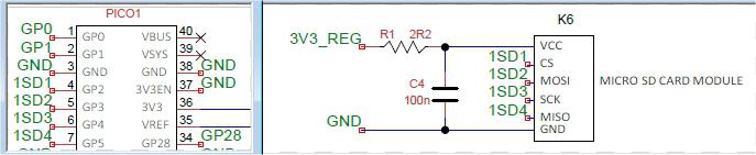 UPDATE: Ok, now I see printed on the bottom OPTION SDCard GP2,GP4,GP3,GP5, so OPTION SDCard 4,6,5,7 (and that works). ~ Edited 2022-08-10 03:23 by lizby PicoMite, Armmite F4, SensorKits, MMBasic Hardware, Games, etc. on fruitoftheshed |
||||
| Mixtel90 Guru Joined: 05/10/2019 Location: United KingdomPosts: 5737 |
It seems to be CS - GP2 SCK - GP6 MOSI - GP3 MISO - GP7 No matter what the circuit says. Sometimes it tells lies. �:) I'm wondering if I put the wrong version of the circuit in the construction pack - or if I'm looking at the wrong SL6 file. The above have come from the SL6. Note that it's the same for both Picos. This is a version 0.2 board I'm looking at. Edited 2022-08-10 03:22 by Mixtel90 Mick Zilog Inside! nascom.info for Nascom & Gemini Preliminary MMBasic docs & my PCB designs |
||||
| matherp Guru Joined: 11/12/2012 Location: United KingdomPosts: 8592 |
SDcard is CS[, clk, mosi, miso] Edited 2022-08-10 03:34 by matherp |
||||
| Mixtel90 Guru Joined: 05/10/2019 Location: United KingdomPosts: 5737 |
As long as you've got one that's working, Lizby. :) I must be looking at a wrong file, I think. Mick Zilog Inside! nascom.info for Nascom & Gemini Preliminary MMBasic docs & my PCB designs |
||||
| lizby Guru Joined: 17/05/2016 Location: United StatesPosts: 3017 |
Thanks. What was written on the board works. I don't think I'll need the SD card on Pico2. option system i2c gp16,gp17 followed by option lcdpanel ssd1306i2c,rl,2 also works, but there's some wierdness with the text--some of the pixels are not displaying. > cls > text mm.hres/2,mm.vres/2-15,"HELLO",cm,1 > text mm.hres/2,mm.vres/2,"THERE",cm,1 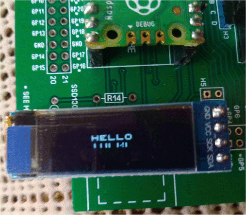 PicoMite, Armmite F4, SensorKits, MMBasic Hardware, Games, etc. on fruitoftheshed |
||||
| Mixtel90 Guru Joined: 05/10/2019 Location: United KingdomPosts: 5737 |
Is there a bit offset value to tweak for that display? IIRC there is on the one I used. Mick Zilog Inside! nascom.info for Nascom & Gemini Preliminary MMBasic docs & my PCB designs |
||||
| Mixtel90 Guru Joined: 05/10/2019 Location: United KingdomPosts: 5737 |
Ah - I've found out why I got the wrong info. I was looking at version 0.2 and you have an original version 0 board. Version 0.2 adds a JDY-40 and micro SD card sockets. It also moves the GP4 and GP5 connections to GP6 and GP7. That change allows access to COM2 on Pico1. I don't appear to have made a construction pack for version 0.2. I was probably trying to squeeze more onto it. :) Mick Zilog Inside! nascom.info for Nascom & Gemini Preliminary MMBasic docs & my PCB designs |
||||
| matherp Guru Joined: 11/12/2012 Location: United KingdomPosts: 8592 |
Correct display type for this display is SSD1306I2C32 |
||||
| lizby Guru Joined: 17/05/2016 Location: United StatesPosts: 3017 |
Thanks--that did the trick. PicoMite, Armmite F4, SensorKits, MMBasic Hardware, Games, etc. on fruitoftheshed |
||||
| lizby Guru Joined: 17/05/2016 Location: United StatesPosts: 3017 |
Mick--what is the purpose of the 2R2 resistor at R1 (power to the SD card)? I didn't have a 2R2, and after looking at the circuit, I just inserted a Dupont wire with pins on each end, not soldered, and the SD card worked. What am I risking if I just put a link at R1? PicoMite, Armmite F4, SensorKits, MMBasic Hardware, Games, etc. on fruitoftheshed |
||||
| Mixtel90 Guru Joined: 05/10/2019 Location: United KingdomPosts: 5737 |
It will often work fine with the 2R2 linked out. Often without the capacitor either. However, there have been issues with *some* combinations of firmware and some SD cards where writes (usually) had problems. Peter originally introduced the CR filter (on the CMM2) as a way to fix this. He used 10uF bypassed by 100nF with a 2R2 resistor. If your SD card works then fine. you don't need the resistor at least. :) It may be worth keeping a capacitor though as some cards can draw relatively high current sometimes. Mick Zilog Inside! nascom.info for Nascom & Gemini Preliminary MMBasic docs & my PCB designs |
||||
| Mixtel90 Guru Joined: 05/10/2019 Location: United KingdomPosts: 5737 |
Shows how popular this board is... ** The regulator connections are wrong. It won't work. ** I'm currently fixing this on the version 0.2 board, probably using the SOT package to get a little heatsink area. Goodness knows how I hadn't spotted it previously. The nearest it gets to working is to use a LF33 regulator but mount it on the bottom of the board as in /out are reversed. Sorry, I'll do better next time. :) Mick Zilog Inside! nascom.info for Nascom & Gemini Preliminary MMBasic docs & my PCB designs |
||||
| lizby Guru Joined: 17/05/2016 Location: United StatesPosts: 3017 |
Glad I'm not using the regulator--just the usb connection with VSYS tied to VBUS on Pico2 (works with USB plugged into either Picomite). Has anyone determined whether you can get 500mA from the Pico USB connection, or just 100mA? ~ Edited 2022-08-10 23:03 by lizby PicoMite, Armmite F4, SensorKits, MMBasic Hardware, Games, etc. on fruitoftheshed |
||||
| Mixtel90 Guru Joined: 05/10/2019 Location: United KingdomPosts: 5737 |
The 3V3 output from a Pico *should* have about 300mA spare for the user. The actual current available will depend on how heavily loaded the RP2040 is, what bits of it are enabled and the clock speed. The recommendation from Raspberry Pi is that you don't exceed 300mA. The current from VBUS, at 5V, will depend on the rating of the USB port that it's plugged into. It's a direct connection. Some computers have a limited current from front connectors but more from rear ones. Whether the Pico negotiates a current over USB I don't know. The current available from VSYS, at 5V, is limited by it having a 1A rated diode in circuit, so even if you had a 2A USB input you couldn't exceed 1A from VSYS. Edited 2022-08-10 23:56 by Mixtel90 Mick Zilog Inside! nascom.info for Nascom & Gemini Preliminary MMBasic docs & my PCB designs |
||||
| lizby Guru Joined: 17/05/2016 Location: United StatesPosts: 3017 |
Thanks for the info. PicoMite, Armmite F4, SensorKits, MMBasic Hardware, Games, etc. on fruitoftheshed |
||||
