
|
|
Forum Index : Microcontroller and PC projects : PWM to +/- 10V
| Page 1 of 4 |
|||||
| Author | Message | ||||
| Tinine Guru Joined: 30/03/2016 Location: United KingdomPosts: 1646 |
Question for the analogue/analog experts: The following has served me well on a 5V system. Will I need to change component values for the same to work on 3.3V? 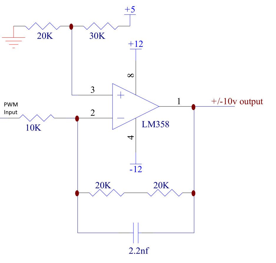 Don't have all of the components with me so can't test. Craig |
||||
| Volhout Guru Joined: 05/03/2018 Location: NetherlandsPosts: 3558 |
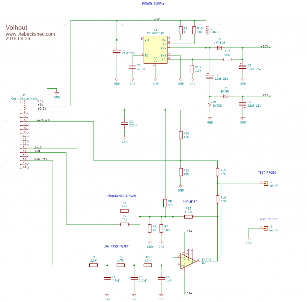 This circuit is making +/-13V from PWM (100kHz) in high gain setting (R3 to GND, R4 to 3V3) and +/- 6V in low gain setting (R3 floating, R4 floating). It also measures back the output voltage. Pinout is for a MX170 backpack circuit board. If you have +/-15V then you don't need the switcher... R6 and R7 can be replaced by a single 91k resistor (harder to get). I hope this helps... Volhout Edited 2022-05-11 21:29 by Volhout PicomiteVGA PETSCII ROBOTS |
||||
| Tinine Guru Joined: 30/03/2016 Location: United KingdomPosts: 1646 |
@Volhout  .... I expected this because I remember that you posted it some time ago. .... I expected this because I remember that you posted it some time ago.I believe that it's more sophistication than I need, though. Not sure that I will benefit from the 2nd and 3rd order stuff. This is a 1KHZ servo-loop where the output is always very erratic. Furthermore, the motor itself kinda acts as a LPF. Thanks for posting though, it would be nice to compare  Craig |
||||
| Tinine Guru Joined: 30/03/2016 Location: United KingdomPosts: 1646 |
Thinking: Switch the 10K to 6.6K and limit the PWM to keep within +/- 10V. Craig |
||||
| Mixtel90 Guru Joined: 05/10/2019 Location: United KingdomPosts: 5739 |
I just experimented on Circuit Simulator. First experiments indicate changing the lower half of the potential divider from 20k to 6k8, feeding it from 3V3 instead of 5V. Not had time to go further. Mick Zilog Inside! nascom.info for Nascom & Gemini Preliminary MMBasic docs & my PCB designs |
||||
| Tinine Guru Joined: 30/03/2016 Location: United KingdomPosts: 1646 |
Oh Cool...Thanks again buddy Just out of curiosity, what do you get if you switch the two series 20K resistors for a 33K and a 27K? I need this Circuit Simulator, I guess Craig |
||||
| Volhout Guru Joined: 05/03/2018 Location: NetherlandsPosts: 3558 |
You go from 40k to 60k, so you get +/-15v out. Which will not be possible when powered from 12v Better use 18k and 22k Edited 2022-05-12 03:22 by Volhout PicomiteVGA PETSCII ROBOTS |
||||
| Mixtel90 Guru Joined: 05/10/2019 Location: United KingdomPosts: 5739 |
Circuit Simulator isn't truly realistic (it's an ideal op-amp and a roughly simulated capacitor), but it's showing that the output is +12 down to -10 for duty cycles of 0.1% to 99.9%. That's approximately the same as the original circuit showed IIRC. I went for a freequency of 1kHz, but that only affects the quality of the output for a given capacitor. Mick Zilog Inside! nascom.info for Nascom & Gemini Preliminary MMBasic docs & my PCB designs |
||||
| matherp Guru Joined: 11/12/2012 Location: United KingdomPosts: 8592 |
Depends on the application but in some you can also use an H-bridge driver then you just need a single +12V supply |
||||
| Tinine Guru Joined: 30/03/2016 Location: United KingdomPosts: 1646 |
The universal standard for industrial servo drives (amplifiers) is a motor command of +/-10V. The drive can be configured in "velocity-mode" or "torque-mode" In VM, the max velocity of the motor might be 3000RPM and so the drive's velocity scaling would be set for 1V = 300RPM. In this mode, the control system doesn't require a full PID, only the "P" (proportional gain). I prefer TM where the motor/drive might be rated for a maximum current of 30A and so the current scaling (gain) is set to 1V = 3A. In this mode, the control system handles the full PID. H-bridge is an interesting idea  Thanks again, guys Craig |
||||
| PeterB Guru Joined: 05/02/2015 Location: AustraliaPosts: 639 |
G'Day Craig If you change the 30k to 26.15k (file the end off a 27k) that will give a voltage of 1.43 at +ve input and -ve input. Then change the 20k + 20k to 60k (27k + 33k) it should give you what you want. Good luck Peter And change 5V to 3.3V. Edited 2022-05-12 12:50 by PeterB |
||||
| Tinine Guru Joined: 30/03/2016 Location: United KingdomPosts: 1646 |
You kiddin' me? I'm talking precision, here....I'll stick it on the surface grinder Many thanks, Pete |
||||
| Tinine Guru Joined: 30/03/2016 Location: United KingdomPosts: 1646 |
Hmmm, I wonder.... If I stick a 50K trimpot (only because I have one) in there and fiddle around in the 26K area, would this effectively provide an offset trim? Not really critical in this application but it's just nice to have a zero-volt output from a 50% duty cycle. Can't get to my breadboard stuff until the weekend. Craig |
||||
| PeterB Guru Joined: 05/02/2015 Location: AustraliaPosts: 639 |
The important parts are 1.43V on +ve input and 60k for the gain. If these are wrong you will get a wrong answer. Would you like me to calculate what would result from just the 26k adjustment? Peter Ein = 3.3V Eout = -6V Ein = 0V Eout = 7.15V That all assumes I remember Ohm's Law. Edited 2022-05-12 15:25 by PeterB |
||||
| Turbo46 Guru Joined: 24/12/2017 Location: AustraliaPosts: 1593 |
Seriously, what sort of precision are you after? Are you wanting to convert 3.3 volts PWM signal to */- 10 volts? Assuming 3.3 volts: Set the + side of the op amp at 1/2 that with a resistor divider. Easy to do with two equal values of resistors in series across the 3.3 volt supply. Not sure what the range of (filtered) output voltage you will get from the PWM - say: 0.3 to 3.0 volts. That is +/- 1.35 volts swing either side of the middle of 3.3 volts (1.65 volts) You now want the op amp gain to be 10/1.35 or 7.4. Choose the input resistor that you want, say the 10k in your circuit and make the feedback resistor 7.4 times that value. Try 75k for a start. Bill PS use a trim pot instead of a file to adjust the value if you need to.  Keep safe. Live long and prosper. |
||||
| PeterB Guru Joined: 05/02/2015 Location: AustraliaPosts: 639 |
To correct 27K to 26.15 no need for a surface grinder or file just stick a 820k in parallel. Bill. I'm not sure your idea will work. Peter |
||||
| phil99 Guru Joined: 11/02/2018 Location: AustraliaPosts: 1795 |
To get that accuracy don't forget the pico pin impedance is in series with the 10k. It's about 40 - 50R, so the resistor will need a little elasticity! (1M trim-pot instead of 820k perhaps?) A 1k trim-pot in the middle of the voltage divider will let you set 0.0V at 50%. |
||||
| Tinine Guru Joined: 30/03/2016 Location: United KingdomPosts: 1646 |
The PWM is actually from the Propeller P2; 14bit @10KHZ Yeah, from my know-nothing-about-opamps view, the original circuit has a gain of 4 and with a max input of 5V, 4 * 5V = 20V (range) 60K of feedback = a gain of 6 and so 6 * 3.3 = near-enough. Craig |
||||
| PeterB Guru Joined: 05/02/2015 Location: AustraliaPosts: 639 |
Bill. I think your idea fails because with 1.65V on the +ve input, there must also be 1.65V on the -ve input. So then the voltage across the 10k is Ein - 1.65 and for Ein = 1.65, Eout must be 1.65 since no current can flow. There was a time when I was quite good at this but today I have used up my supply of scrap paper just trying to work out how to work it out. I had to remember simultaneous equations ???????? And don't forget we are going to have a glass of red one day. Peter |
||||
| Turbo46 Guru Joined: 24/12/2017 Location: AustraliaPosts: 1593 |
Hi Peter, You're correct of course. 1.65 volts is the new zero so the swing will be about that. I also used to be good at this but I've killed too many brain cells.  Things have conspired against me so far but I haven't forgotten. Bill Keep safe. Live long and prosper. |
||||
| Page 1 of 4 |
|||||
