
|
|
Forum Index : Microcontroller and PC projects : PicoMite/PicoMiteVGA V5.07.05 betas
| Author | Message | ||||
| Plasmamac Guru Joined: 31/01/2019 Location: GermanyPosts: 573 |
Hi, isnt the "Load data to pointer" not implemented ? iam awaiting my sd card conector , so i cant say it really. thx Plasma |
||||
| matherp Guru Joined: 11/12/2012 Location: United KingdomPosts: 10273 |
Same as all the Micromite family - just confirmed on a MM2 If you mean the CMM2 load data and save data commands then these are not in the PicoMite |
||||
| vegipete Guru Joined: 29/01/2013 Location: CanadaPosts: 1129 |
I think MMB4W does it too. Visit Vegipete's *Mite Library for cool programs. |
||||
| Bleep Guru Joined: 09/01/2022 Location: United KingdomPosts: 625 |
Hi Peter, I'm using Picomite 5.070514 with a LCDPANEL ILI9481. It appears that the most recent update has upset the rgb colours. If I use an RGB value less than 100 there is no effect on the screen, so for example if I do :- CLS RGB(90,0,0) the screen stays black. Similarly CLS RGB(90,90,90) etc, as soon as I go above 100 I start to see colour and it appears to be compressed, scaled between ~90-255, rather than 0-255. I also have a ILI9481IPS and a ILI9341 and these appear to be behaving as expected. Could you have a look and make sure I'm not going barmy. Also the IPS colour looks a bit washed out, I was expecting the 9481IPS to be better, brighter colours, than the standard 9481, maybe it's just because it's cheap. :-) Thanks. Regards, Kevin. Edited 2022-07-15 22:24 by Bleep |
||||
| Volhout Guru Joined: 05/03/2018 Location: NetherlandsPosts: 5072 |
Have you accidentally loaded the VGA version? The VGA version only supports 16 colors, but may also support a LCD. Volhout PicomiteVGA PETSCII ROBOTS |
||||
| matherp Guru Joined: 11/12/2012 Location: United KingdomPosts: 10273 |
Does this precise panel work with a previous release. Is this the Raspberry Pi display with the 26 pin header 13x2? |
||||
| Bleep Guru Joined: 09/01/2022 Location: United KingdomPosts: 625 |
Hi Peter, Yes it's a Raspberry Pi display with a 26 pin header on the back 2x13 female. I've gone back to 5.07.04 and it's the same, so presumably it's a problem with my display, I'd never noticed before, with what I was displaying on it, but I re-purposed it and suddenly I noticed all the colours were different from the display I had been using. :-( never mind. Regards, Kevin. |
||||
| Bleep Guru Joined: 09/01/2022 Location: United KingdomPosts: 625 |
Hi Peter, I managed to borrow a second one of these displays (ILI9481 Raspberry Pi display with a 26 pin header on the back 2x13 female) and it's behaving the same as mine? Any colour set to less than ~90 is almost invisible, you can just detect some change, but it's minute, for example CLS RGB(127,82,0) is hardly visible mud red, I think it should be dimmed orange, it is on other displays I have. If this is a generic display problem, that's fine, it was cheap, then I'll redefine them to offset by 90 and re-scale between 90-255, otherwise could you have a quick look, this is using Picomite 5.07.04 and also 5.07.05.14. Thanks, Kevin. :-) |
||||
| matherp Guru Joined: 11/12/2012 Location: United KingdomPosts: 10273 |
PicoMite V5.07.05b15 https://geoffg.net/Downloads/picomite/PicoMite_Beta.zip New command OPTION HEARTBEAT ON/OFF Fixes bug in GUI TEXTBOX ACTIVATE not accepting # in the control number Checked the ILI9481 display and mine acts the same. Have tried different settings for gamma but no improvement - just a crap display unless someone can find some better initialisation sequence |
||||
Quazee137 Guru Joined: 07/08/2016 Location: United StatesPosts: 593 |
I have been using the ILI9481 Raspberry Pi display on my MM170 hatstands and now switching over to pico. Here is a few pic's 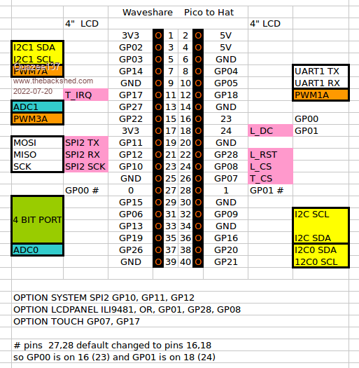  .png)  I have Peters Clock program running on it. |
||||
| Bleep Guru Joined: 09/01/2022 Location: United KingdomPosts: 625 |
Hi Peter, Thanks very much for confirming it's a display problem, I'll adjust the colours as appropriate when using that display. I have loaded your latest V5.07.05b15 on to the Pico that is using that display and all seems to be working great, :-) Thanks. Regards, Kevin. |
||||
| vegipete Guru Joined: 29/01/2013 Location: CanadaPosts: 1129 |
Looking at the source code for Draw.c on Github, I think I see why. Tunneling down the DrawLine routine, eventually flow gets to DrawRectangleMono (or DrawRectangleColour) as the primitives used to set individual pixels. These always draw _something_ on the screen because the range of values is clamped to the screen. A possible change is to 1] size sort x & y coordinates first (Why does the sort appear twice in both routines?) 2] exit without drawing anything if x1 >= HRes || x2 < 0 || y1 >= VRes || y2 < 0 3] clamp to screen 4] draw the rectangle 5] enjoy a cold one (or a hot cuppa) However, I haven't followed much other code to see how that might affect everything else that uses the DrawRectangle_xxx routines. Visit Vegipete's *Mite Library for cool programs. |
||||
| matherp Guru Joined: 11/12/2012 Location: United KingdomPosts: 10273 |
That code is in every version of MMbasic - MM2, MM+, MMX etc. so I'm not going to change it sorry. Another possible change is for the Basic programmer not to write outside the screen boundaries  |
||||
| circuit Senior Member Joined: 10/01/2016 Location: United KingdomPosts: 276 |
PicoMite V5.07.05b15 I have a problem loading the SSD1963_7 screen driver with b15. OPTION LCDPANEL SSD1963_7, RL Device reboots then OPTION LIST shows; OPTION LCDPANEL SSD1963_5A, RL I am not mistyping - I tried it three times and got the same. I then reloaded 5.07.04 and the problem cleared. Reloading b15 produced the problem again. |
||||
| matherp Guru Joined: 11/12/2012 Location: United KingdomPosts: 10273 |
The driver will be correct just the list output wrong |
||||
| circuit Senior Member Joined: 10/01/2016 Location: United KingdomPosts: 276 |
Unfortunately, it appears not - the screen won't calibrate. �GUI CALIBRATE shows the normal calibration screen but then as soon as I touch the first calibration mark the screen goes into an infinite scrolling loop, not broken until I cycle the power. I have just tried SSD1963_7A and that works okay and I am up and running and calibrated �but the OPTION LIST now shows SSD1963_7, not 7A. For clarity, I have only ever used SSD1963_7, I have never had to use 7A with the five SSD1963 screens that I have on a range of MicroMite and derivative devices. Edited 2022-07-24 20:38 by circuit |
||||
| matherp Guru Joined: 11/12/2012 Location: United KingdomPosts: 10273 |
That is nothing to do with the screen driver. Touch the screen very briefly and it should work. Known issue |
||||
| circuit Senior Member Joined: 10/01/2016 Location: United KingdomPosts: 276 |
It is fascinating how some combination of circumstances can cause issues such as this. �I have installed five SSD1963 screens, with various processors and updated firmware many times, re-entering option lists left, right and centre and never encountered a problem...and then... Thank you for your attention, explanations and time on a Sunday morning! (and again thank you for the heartbeat option). Edited 2022-07-24 22:05 by circuit |
||||
| thwill Guru Joined: 16/09/2019 Location: United KingdomPosts: 4308 |
Hi folks, I've checked the manual and can't find it, but is anyone aware of a way on the PicoMite VGA to PRINT to the USB console and not to the VGA display ? On a CMM2 I would do: Option Console Serial Print "Only on the serial console" Option Console Screen Print "Only on the VGA display" Option Console Both Print "On both serial console and display" If this functionality doesn't exist in some form then I don't suppose you could add it please Peter as it's very useful for debugging ? Best wishes, Tom MMBasic for Linux, Game*Mite, CMM2 Welcome Tape, Creaky old text adventures |
||||
| Bleep Guru Joined: 09/01/2022 Location: United KingdomPosts: 625 |
Hi, I'm trying to get Geoffs DDS Sig Gen working on a PicoMite and I've hit a problem that I can't solve. my options are PicoMite MMBasic Version 5.07.05b14 Copyright 2011-2022 Geoff Graham Copyright 2016-2022 Peter Mather > option list OPTION SYSTEM SPI GP10,GP11,GP12 OPTION COLOURCODE ON OPTION CPUSPEED (KHz) 252000 OPTION DISPLAY 61, 195 OPTION LCDPANEL ILI9341, LANDSCAPE,GP19,GP18,GP17,GP6 OPTION TOUCH GP21,GP20 GUI CALIBRATE 0, 3887, 100, -896, 654 when I run this code snippet, all is well. SetPin 6,5,4,SPI SPI Open 1000000, 2, 16 SPI Write 1, &H8080 SPI Close When I run this full driver segment which Peter originally supplied, all is well. Option EXPLICIT Option DEFAULT NONE ' ' AD9833 Control Bits ' Const B28%=&H2000 Const HLB%=&H1000 Const FSELECT%=&H800 Const PSELECT%=&H400 Const RESET%=&H100 Const SLEEP1%=&H80 Const SLEEP12%=&H40 Const OPBITEN%=&H20 Const DEV2%=8 Const MODE%=2 ' ' Micromite pin allocation ' Const CS%=17 ' pin for MCP41010 chip select (CS) pin on module Const FSY%=19 ' pin for AD9833 chip select(FSY) pin on module ' ' Output modes ' Const TRIANG%=1 Const SINE%=0 Const SQUARE%=-1 ' SetPin CS%,dout SetPin FSY%,dout Pin(CS%)=1 Pin(FSY%)=1 SetPin 6,5,4,SPI SPI open 1000000,2,16 'has to be mode 2 for AD9833, MCP41010 doesn't seem to mind ' updateamplitude(255) 'scale output 100% Do updatefrequency(20000,SQUARE%) '20KHz square wave Pause 2000 updatefrequency(10000,TRIANG%) '10KHz triangle wave Pause 2000 updatefrequency(40000,SINE%) '40KHz sine wave Pause 2000 Loop End ' Sub updateamplitude(i%) ' Sets the output of the MCP41010 digital potentiometer (0-255) Local j%=&H1100 Or (i% And 255) Pin(CS%)=0 SPI write 1,j% Pin(CS%)=1 End Sub ' Sub updatefrequency(fin%, wave%) 'Sets the frequency (Hz) and waveform of the AD9833 (Sine:wave%=0, Triangl Local oscillator%=25000000 'Crystal frequency Local twoby28%=268435456 '2^28 Local f%=(fin%*twoby28%)\oscillator% Local c%=0 Local f1%=(f% And &H3FFF) Or &H4000 Local f2%=(f%>>14) Or &H4000 Local p%=&B1100000000000000 If wave% =1 Then c%=c% Or MODE% If WAVE%=-1 Then c%=c% Or SLEEP12% Or OPBITEN% Or DEV2% Pin(FSY%)=0 SPI write 5,c% Or RESET% Or B28%,f1%,f2%,p%,c% ' print bin$(c% OR RESET% OR B28%,16)," ",bin$(f1%,16)," ",bin$(f2%,16)," ",bin$(p%,16)," ",bin$(c%,16) Pin(FSY%)=1 End Sub However when I try to run the version of Geoffs program to drive the Signal Generator I get this error, unfortunately I don't know what it means. [417] SPI Open 1000000, 2, 16 Error : Not all pins set for SPI If I comment out all the SPI calls in the code, the software all runs fine, now that I've fixed all the compatibility problems, all the screens are produced correctly and function, I simply cant get past this error. Full code attached in zip. SigGen.BAS.zip Any hints as to what might be the problem appreciated. Regards, Kevin. PS. I think I've just found that it might be being caused by the multiple SPI Open..., SPI Write..., SPI Close calls? Edited 2022-08-09 03:45 by Bleep |
||||
| The Back Shed's forum code is written, and hosted, in Australia. | © JAQ Software 2025 |
