
|
|
Forum Index : Microcontroller and PC projects : Will the Pico directly drive this MOSFET?
| Page 1 of 4 |
|||||
| Author | Message | ||||
| Tinine Guru Joined: 30/03/2016 Location: United KingdomPosts: 1646 |
Deciphering data-sheets is not a strong point for me  Craig FQP30N06L.pdf |
||||
| matherp Guru Joined: 11/12/2012 Location: United KingdomPosts: 11499 |
Yes but with unspecified on resistance and therefore current capability |
||||
| Tinine Guru Joined: 30/03/2016 Location: United KingdomPosts: 1646 |
I only need to sink 2A....is that what you mean? Craig |
||||
| lizby Guru Joined: 17/05/2016 Location: United StatesPosts: 3782 |
I bought some of those nearly 7 years ago and have successfully used them with the PICAXE (at 4V5) for a few amps at 12V. What drain-source voltage? I would think that they would work at 3V3 for a few amps. I'm currently using IRLB8721PBF and IRL540 for 12V and a few amps directly from Picomite (not PWMed, though that should work as well). ~ Edited 2022-06-04 03:21 by lizby PicoMite, Armmite F4, SensorKits, MMBasic Hardware, Games, etc. on FOTS |
||||
| Tinine Guru Joined: 30/03/2016 Location: United KingdomPosts: 1646 |
28V....Ah-ha my local stockist has both of those devices. I'll head over there tomorrow morning....many thanks  Craig |
||||
| CaptainBoing Guru Joined: 07/09/2016 Location: United KingdomPosts: 2171 |
my heated bed uses one to switch 27V at 4.3A no probs. 25Hz PWM no heat sink and no heat in the device detectable by pinching Edited 2022-06-04 03:44 by CaptainBoing |
||||
| Tinine Guru Joined: 30/03/2016 Location: United KingdomPosts: 1646 |
Music to my...umm..eyes  It's the heat that I want to minimise/eliminate It's the heat that I want to minimise/eliminate Craig |
||||
| Tinine Guru Joined: 30/03/2016 Location: United KingdomPosts: 1646 |
Ended up with the FQP30N06L and it's a no-go with 3v3 PWM. Guess I need a proper gate driver(?)  Craig |
||||
| Mixtel90 Guru Joined: 05/10/2019 Location: United KingdomPosts: 8904 |
Have you tried slowing the PWM down? Just to test, not as a change to your design. VGS(th) is 2V5 max and the PicoMite has totem pole outputs so I think it should work at *some* frequency. Watch the pinout too - it's GDS, not gate in the middle. Edited 2022-06-09 01:09 by Mixtel90 Mick Zilog Inside! nascom.info for Nascom & Gemini Preliminary MMBasic docs & my PCB designs |
||||
| CaptainBoing Guru Joined: 07/09/2016 Location: United KingdomPosts: 2171 |
I drive them at 3V3, 25Hz from a '170 with no problems at all. No series or pull down resistor - literally direct driven from the IO pin could be speed related as Mick points out above - what freq are you driving at? have you scoped the gate to see what the voltage is? bench test the FET check it isn't dead - MOSFETs are tough when doing what they do, but let's not forget they are FETs and are easily killed - I always wear a stat-strap when handling FETs and chips. Don't be offended: It's an N type device so is best deployed in common source mode with the load between VDD and the drain - not carved in stone but for N type power driver it is my preferred hook-up and what I have used in all my designs. If you have it between VDD and the load, you might not be getting a very good Vgs and the th bit will be raised accordingly which might easily stop the thing turning on, or worse being pushed back up its trans-conductance curve where it might start dissipating. It could die very quickly in worst cases there. Illustration; if RDS could only get down to say 0.1R, at 24V that could theoretically be 240A. Unlikely your PSU would give that (batteries might) but a big spike in current would fry it, even given its a 32A device... but not at 24V (768W dissipation) post your schematic from Pi to FET I have used dozens of FQP30s without any issues ever. I am curious now, there has to be a reason Edited 2022-06-09 01:38 by CaptainBoing |
||||
| Tinine Guru Joined: 30/03/2016 Location: United KingdomPosts: 1646 |
Found a graphic that is similar. I am at 24V, though. Strange this is, though, I pull the PWM wire away from the Pico and in free air, the FET starts conducting 4A(!!!)...Put my finger on the end of the wire where the PWM is supposed to go and the load current is reduced to ~2A...Clearly confused here  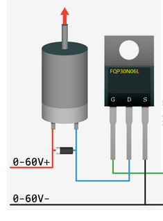 Craig |
||||
| Tinine Guru Joined: 30/03/2016 Location: United KingdomPosts: 1646 |
Oh, PWM is 25HZ also. |
||||
| CaptainBoing Guru Joined: 07/09/2016 Location: United KingdomPosts: 2171 |
that is normal for FETs. because the gate is insulated, you put a charge on it and it will stay there until you take it away. There is enough charge in the air for it to build up on the gate and thing will turn on as you are seeing (I show this here with FQP30s: https://youtube.com/clip/UgkxPUK-uO7D5RpuBlJmOdGmBh1Tdvv9xaVk ) �be warned though the charge may not be good enough for a hard 27mR and you might get over-dissipation so in your circuit, you have +0-24V and -0-24V? if the source is at -24V, the gate voltage will vary between 24V and 27.3V (relative to S). so when the pico is driving at 0V so the thing will always be on. This incidentally is a danger zone - rule of thumb, Gate voltage should be <20V Edited 2022-06-09 01:56 by CaptainBoing |
||||
| Tinine Guru Joined: 30/03/2016 Location: United KingdomPosts: 1646 |
+24V  |
||||
| Tinine Guru Joined: 30/03/2016 Location: United KingdomPosts: 1646 |
Cap'n....Your bed heater sounds exactly what I have but it's a coach-seat heater. |
||||
| Mixtel90 Guru Joined: 05/10/2019 Location: United KingdomPosts: 8904 |
Forget the PWM. What happens if you just switch the pico pin on and off? Or slow the PWM down to a couple of Hz. I trust this isn't a fake mofet with VGS(th) at over 3V? Mick Zilog Inside! nascom.info for Nascom & Gemini Preliminary MMBasic docs & my PCB designs |
||||
| CaptainBoing Guru Joined: 07/09/2016 Location: United KingdomPosts: 2171 |
to avoid confusion, this is your circuit(?) 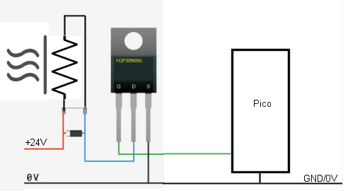 Edited 2022-06-09 02:12 by CaptainBoing |
||||
| Tinine Guru Joined: 30/03/2016 Location: United KingdomPosts: 1646 |
I tried connecting directly to 3.3V...nothing. Pack of 5 arrived this morning from rs-online |
||||
| Tinine Guru Joined: 30/03/2016 Location: United KingdomPosts: 1646 |
Exactly, except the load is resistive (heating element) |
||||
| CaptainBoing Guru Joined: 07/09/2016 Location: United KingdomPosts: 2171 |
sorry I updated the picture between times. absolutely nothing wrong with your design. precisely the same as my bed heater except I am at 27V and driving with a '170 micromite. As mick said above, test the FET in isolation: attach a wire to the gate and take it to 0V. Measure the voltage between D & S, it should be 24V (the FET is off) Now connect the gate to 3V3 and measure the voltage between D & S - it should be (ideally) 0V (The FET is switched on hard... 3V3 is above VGSth of 2.5V and RDS is a few milli-ohms) if all the above checks out, the problem has to be something with the way the Pico is driving. connect the gate to your I/O pin and set it high then low. Do the checks again in each state. if all is OK then the problem has to be with your PWM setup. |
||||
| Page 1 of 4 |
|||||
| The Back Shed's forum code is written, and hosted, in Australia. | © JAQ Software 2026 |
