
|
|
Forum Index : Microcontroller and PC projects : Waveshare LCD Picomite
| Page 1 of 2 |
|||||
| Author | Message | ||||
| Rickard5 Guru Joined: 31/03/2022 Location: United StatesPosts: 463 |
7-8 weeks ago I got one of those Waveshare Pico LCD Modules, and thought it was the neatest LCD Package for a bunch of projects I want to do, then when I realized there was no easy to Access the unused IO pins so I may be the last one to figure out to do my pico pins like this : but I got there in the end 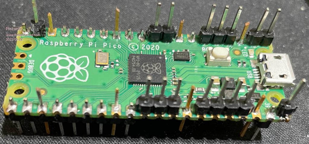 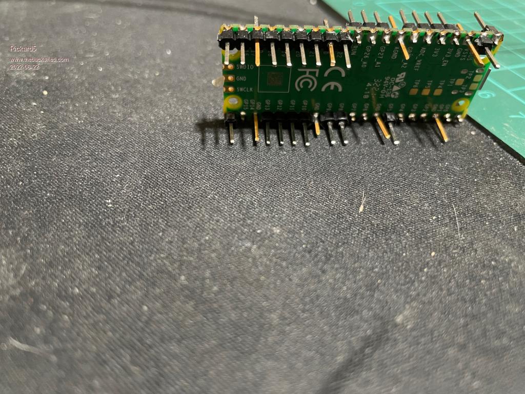 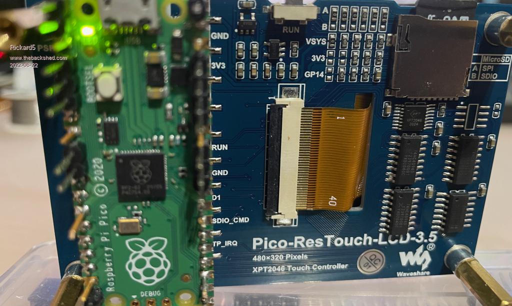  I may be Vulgar, but , while I'm poor, I'm Industrious, Honest, and trustworthy! I Know my Place |
||||
| Mixtel90 Guru Joined: 05/10/2019 Location: United KingdomPosts: 7833 |
That's kinda cool... :) It also illustrates rather nicely just how few I/O you have left. Mick Zilog Inside! nascom.info for Nascom & Gemini Preliminary MMBasic docs & my PCB designs |
||||
| cosmic frog Guru Joined: 09/02/2012 Location: United KingdomPosts: 302 |
That's Spiky! You could call it the PicoSpike  Dave. |
||||
| Mixtel90 Guru Joined: 05/10/2019 Location: United KingdomPosts: 7833 |
Picopine? Mick Zilog Inside! nascom.info for Nascom & Gemini Preliminary MMBasic docs & my PCB designs |
||||
| Rickard5 Guru Joined: 31/03/2022 Location: United StatesPosts: 463 |
It does only leave 11 GPI/O pins available, but that's plenty for some meaningful Projects. I'm real interested in the idea if it's possible (and I know this may sound stupid), of offloading the I/O to another Pico and using the pico in the Waveshare as UI like almost an over simplified Cluster! Edited 2022-06-22 22:33 by Rickard5 I may be Vulgar, but , while I'm poor, I'm Industrious, Honest, and trustworthy! I Know my Place |
||||
| Mixtel90 Guru Joined: 05/10/2019 Location: United KingdomPosts: 7833 |
That's not difficult. You can link them using either I2C or COM ports. Lizby has done a lot of work on this. Mick Zilog Inside! nascom.info for Nascom & Gemini Preliminary MMBasic docs & my PCB designs |
||||
| lizby Guru Joined: 17/05/2016 Location: United StatesPosts: 3349 |
Picomite serial client and more coming. PicoMite, Armmite F4, SensorKits, MMBasic Hardware, Games, etc. on fruitoftheshed |
||||
| vegipete Guru Joined: 29/01/2013 Location: CanadaPosts: 1129 |
That's my plan for a project. Although probably not a Pico as the controller. I intend to put another PCB between the Pico and the LCD display, and use stacking headers (for example) to link it all together. 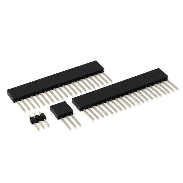 Visit Vegipete's *Mite Library for cool programs. |
||||
| Rickard5 Guru Joined: 31/03/2022 Location: United StatesPosts: 463 |
That was my my original plan to spin up a board that would mount on the top of the pico or between the pico and the waveshare, but the problem become if you try to wedge it between the pico and waves hate you lose too much interconnect pin length so on top would be Ideal then once soldered to the pico the pins could be clipped to shorten up the whole package. and the second problem is I've tried to learn PCB CAD packages, and apparently I'm too stupid top grasp the concept of modern PCB CAD packages, after 22 years of AutoCad 2000, I can't negotiate the relativity simple task of of laying out a 40 pin DIP Breakout board and getting it ordered from China I may be Vulgar, but , while I'm poor, I'm Industrious, Honest, and trustworthy! I Know my Place |
||||
| lizby Guru Joined: 17/05/2016 Location: United StatesPosts: 3349 |
What's your breakout board intended to do? PicoMite, Armmite F4, SensorKits, MMBasic Hardware, Games, etc. on fruitoftheshed |
||||
| lizby Guru Joined: 17/05/2016 Location: United StatesPosts: 3349 |
Rick--note (if I may): when you quote someone, it makes it easier for others to follow if you delete all in the quoted material except for what is needed to provide context for what you yourself say. PicoMite, Armmite F4, SensorKits, MMBasic Hardware, Games, etc. on fruitoftheshed |
||||
| lizby Guru Joined: 17/05/2016 Location: United StatesPosts: 3349 |
Regarding Rick's idea of a picomite with display stacked on a picomite with I/O, with, say, only 5V, 0Vs, and Rx and Tx linking, what would be the best way to power the second picomite from the USB on the first? Aside from the 0Vs, would you need anything more than a power Schottky diode (say 2A SR260) between VBUS (pin 40) on the USB-powered pico and VSYS (pin 39) on the unpowered one? PicoMite, Armmite F4, SensorKits, MMBasic Hardware, Games, etc. on fruitoftheshed |
||||
| lizby Guru Joined: 17/05/2016 Location: United StatesPosts: 3349 |
Duplicate post Edited 2022-06-24 02:52 by lizby PicoMite, Armmite F4, SensorKits, MMBasic Hardware, Games, etc. on fruitoftheshed |
||||
| Mixtel90 Guru Joined: 05/10/2019 Location: United KingdomPosts: 7833 |
Connect VSYS on PicoMite A (the one getting power from the USB) to VSYS on PicoMite B (the other one). That will take the 5V supply from one and connect it to the 5V input of the other. No diodes are needed because PicoMites contain a forward-biased diode from VBUS to VSYS. It doesn't matter which you connect to USB, it will power both. If you connect both to USB then there will be no damage to PC USB ports because the diodes will be reverse-biased. In addition to the above you would need GND and a COM port's TX and RX lines. They should be crossed over, TX to RX and vice versa. To avoid possible problems while playing it might be prudent to link them via 270R resistors. Edited 2022-06-24 03:17 by Mixtel90 Mick Zilog Inside! nascom.info for Nascom & Gemini Preliminary MMBasic docs & my PCB designs |
||||
| lizby Guru Joined: 17/05/2016 Location: United StatesPosts: 3349 |
I forgot about crossover of Tx & Rx, thanks. Too bad the pico doesn't permit them to be switched in software. Just a little mix-up, though; literally. PicoMite, Armmite F4, SensorKits, MMBasic Hardware, Games, etc. on fruitoftheshed |
||||
| hitsware2 Guru Joined: 03/08/2019 Location: United StatesPosts: 719 |
 my site |
||||
| pwillard Guru Joined: 07/06/2022 Location: United StatesPosts: 313 |
Nice... � Here is how I �solve it... with a Pimoroni PicoLipo  Edited 2022-06-24 09:10 by pwillard |
||||
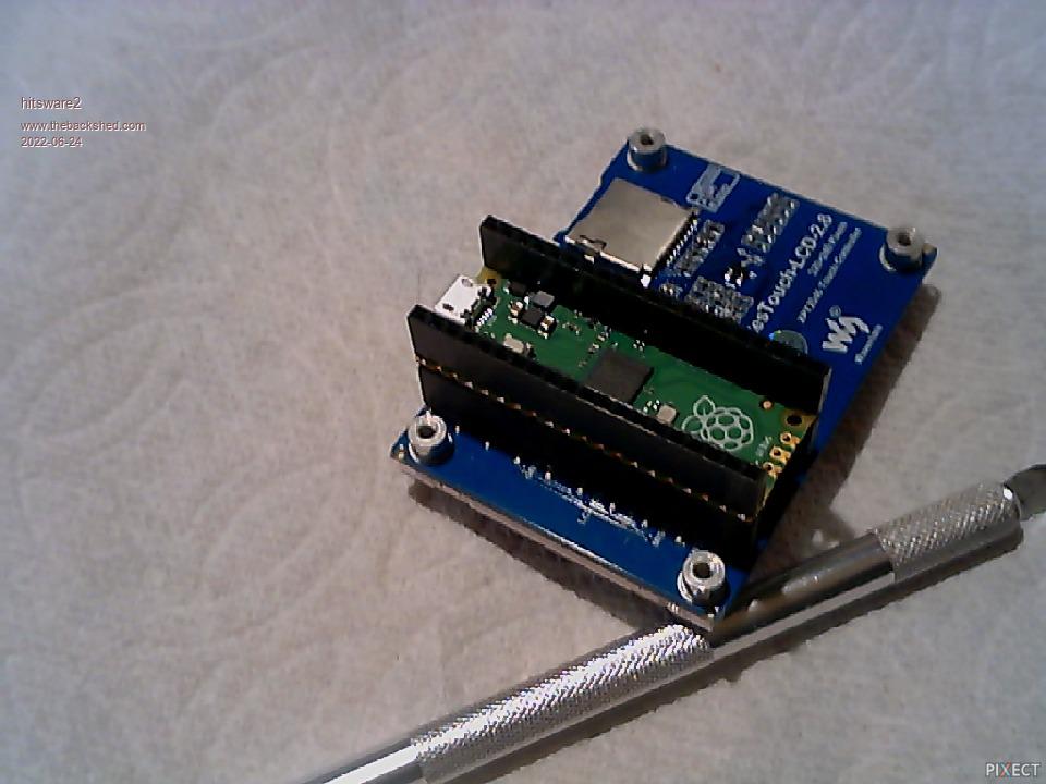
| lizby Guru Joined: 17/05/2016 Location: United StatesPosts: 3349 |
Proof of concept of PicoMite display with 2nd PicoMite for I/O PicoMite, Armmite F4, SensorKits, MMBasic Hardware, Games, etc. on fruitoftheshed |
||||
| pwillard Guru Joined: 07/06/2022 Location: United StatesPosts: 313 |
Wow... a cool idea. I might need to give that a try... the price is right. |
||||
| Page 1 of 2 |
|||||
| The Back Shed's forum code is written, and hosted, in Australia. | © JAQ Software 2025 |
