
|
|
Forum Index : Microcontroller and PC projects : Pico 100 PLC - another crazy idea...
| Author | Message | ||||
| Mixtel90 Guru Joined: 05/10/2019 Location: United KingdomPosts: 8911 |
A sort of baby PLC. Intended for 24V DC supply Serial port can be used to drive a second unit as slave I/O 3 Analogue inputs via potential dividers (assumed to be 0-10V) 12 Digital inputs via potential dividers (handle up to about 30V) 1 Active low digital output, 100mA? 6 clean contact outputs can be relays or SSRs, the electrical clearances should be ok up to 240V mains if the board is mounted in a box. Output terminals are 12A rated pluggable types Input terminals are also pluggable types Of course, it's 100x100mm :) It might need a bit of additional protection on the inputs, but this is just an idea. 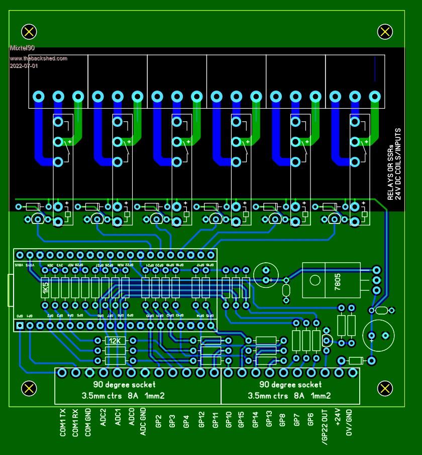 Mick Zilog Inside! nascom.info for Nascom & Gemini Preliminary MMBasic docs & my PCB designs |
||||
| phil99 Guru Joined: 11/02/2018 Location: AustraliaPosts: 3291 |
"It might need a bit of additional protection on the inputs" 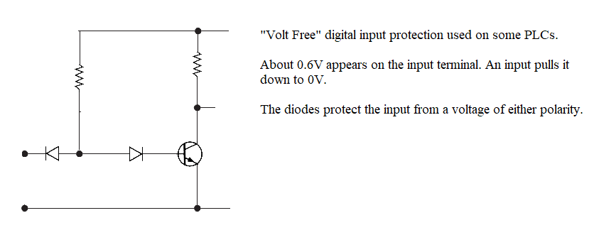 |
||||
| pwillard Guru Joined: 07/06/2022 Location: United StatesPosts: 341 |
A problem that plagued me when I did stuff like this was the impact from the AC load would end up affecting my Micro's performance, aka glitches. Granted... I barely knew what I was doing at the time... but there was a definite "feedback" issue. |
||||
| Tinine Guru Joined: 30/03/2016 Location: United KingdomPosts: 1646 |
I am a fan of these PCB-Mount fuses (cost pennies). PCB_mount_fuse.pdf  Craig |
||||
| Mixtel90 Guru Joined: 05/10/2019 Location: United KingdomPosts: 8911 |
This isn't likely to be of much interest commercially anyway. Look at the time and labour cost involved in soldering all those components and you realize that ordering a ready made unit from RS or somewhere isn't really all that much more expensive. It might be fun for a hobbyist though. As such I'm not particularly bothered about input protection. The Pico board is cheap enough to just swap out if you blow one up - it would cost more than a new Pico to add the extra components. :) Also, I think that for someone who is learning, active low inputs and outputs are the "wrong way round". They are fine technically, but not logical. I'm unlikely to build this, by the way - I've no use for one. It's just a design to play with. :) Here's a revision where I got the GP inputs in order, gave the outputs series & pull-down resistors and added a little display to indicate inputs and outputs or whatever (because there were two pins left for I2C :) Not sure if that display has its own pull-ups though.). Incidentally - the only reason it has a 24VDC supply is that some SSRs in particular aren't available with 5V inputs (and low voltage relay coils need more current). It makes it look like an industrial unit too. :) 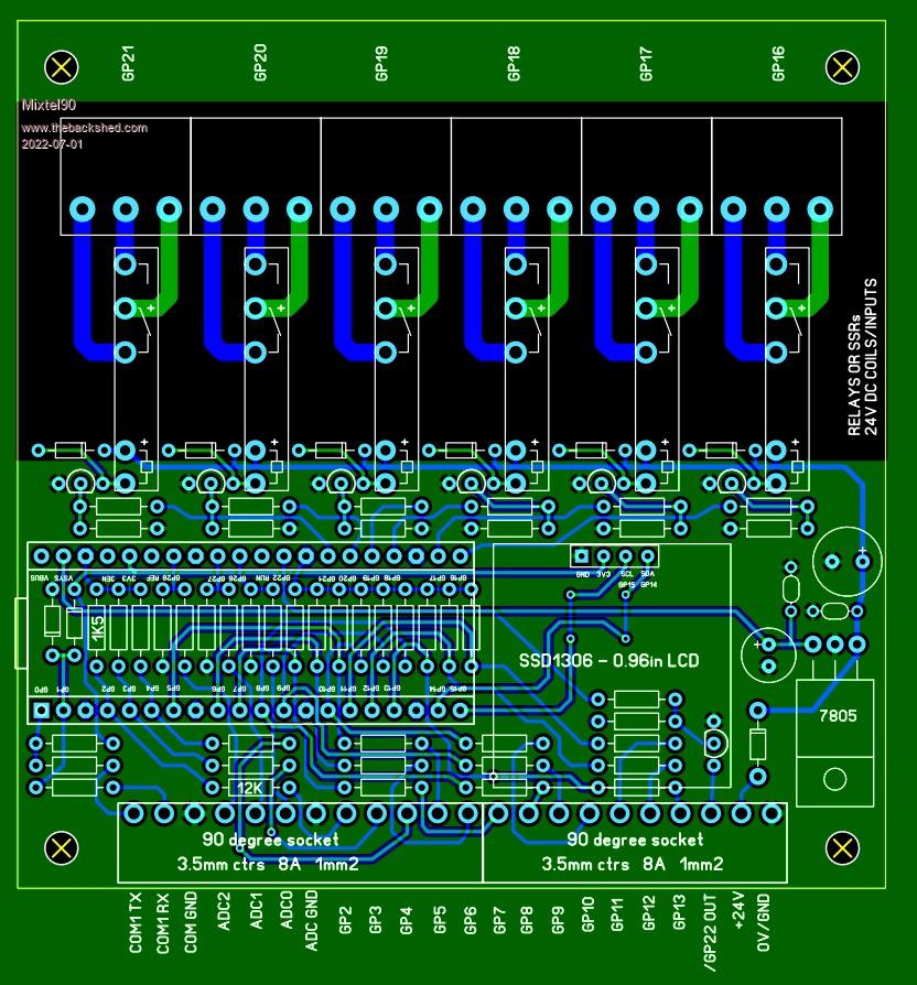 EDIT: This version also has protection on the serial port connection. I thought it might be a good idea. :) Edited 2022-07-01 16:51 by Mixtel90 Mick Zilog Inside! nascom.info for Nascom & Gemini Preliminary MMBasic docs & my PCB designs |
||||
| lizby Guru Joined: 17/05/2016 Location: United StatesPosts: 3784 |
Which SSRs are you looking at with that footprint? PicoMite, Armmite F4, SensorKits, MMBasic Hardware, Games, etc. on FOTS |
||||
| Mixtel90 Guru Joined: 05/10/2019 Location: United KingdomPosts: 8911 |
There are a lot. Typical from RS The SSRs are all NO, of course, so just ignore the NC contact. You can also get electro-mechanical relays in the same footprint. NO, NC and C/O contacts but all single pole. Mick Zilog Inside! nascom.info for Nascom & Gemini Preliminary MMBasic docs & my PCB designs |
||||
| lizby Guru Joined: 17/05/2016 Location: United StatesPosts: 3784 |
Right, so I guess it's the relays with that footprint I'd like a link to, not the SSRs. FWIW, I just received a couple of these SSR modules to test (4-SSR units). PicoMite, Armmite F4, SensorKits, MMBasic Hardware, Games, etc. on FOTS |
||||
| Mixtel90 Guru Joined: 05/10/2019 Location: United KingdomPosts: 8911 |
The Finder 34 series is this format. Several other manufacturers make them too. Those SSR modules look like the same 28x5 footprint. :) Mick Zilog Inside! nascom.info for Nascom & Gemini Preliminary MMBasic docs & my PCB designs |
||||
| Volhout Guru Joined: 05/03/2018 Location: NetherlandsPosts: 5931 |
Everybody has it's own experience and application. Hard to make the design robust against all. - I see a lot of drivers...ULN2003 ? - The pico may consume 50mA(126MHz)-100mA(378MHz) from 5V, especially with OLED. Assume up to 2W dissipation in the LM7805. Heatsink ? Switching (I used a MC34063 and 7 components, cheap and available) - With so many input resistors...resistor array ? - If you put an OLED, why not minimal 2 switches next to it (select/modify) - have not seen schematics, but with 0-3.3V ADC inputs, with a suitable pullup, a suitable pulldown, and a suitable series resistor you can make +/- 10V inputs. - A PLC without RUN/STOP switch ? That is real modern.... � Just thoughts... Edited 2022-07-02 17:44 by Volhout PicomiteVGA PETSCII ROBOTS |
||||
| Mixtel90 Guru Joined: 05/10/2019 Location: United KingdomPosts: 8911 |
It's all a game. :) - I considered the ULN but it brings its own space limitations. The drivers tuck away neatly between the relays/SSRs. - A switching reg would be ideal (I know the exact one - and it's the same pinout), but a simple aluminium L bracket might be enough heatsink. I didn't really give it much consideration. - A resistor array would be fine for the pull-down resistors. The series resistors I'm not sure... Once again, packages bring their own limitations on where you can put them - and restrict what you can do. Independent series resistors are more flexible. - The OLED is there simply because I had two spare pins and it looked like a good idea at the time as there's no room left for I/O indication LEDs. :) There are no more pins left for buttons. - The industry standards for instrumentation are generally 2-10V or 4-20mA. 0-10V is dead easy so I included that. 10-0-10 is generally for positioners and I doubt if something like this would ever be used for that. The outputs are unsuitable for precise control, they can only do bang-bang. - No run/stop as I've no more inputs. :) I've not even been able to wire the RUN pin to anywhere sensible. (Yet) You've not seen schematics 'cos they are only in my head. :) Originally I wanted opto-isolated AC/DC inputs, which is quite possible, but you'd only get about four on the board so I dropped that idea. I'm not willing to go above 100x100 - that's part of the challenge. :) I've considered rearranging the outputs with common feeds to allow a bit less space. That way I might be able to house the whole thing in a Hammond box. Mick Zilog Inside! nascom.info for Nascom & Gemini Preliminary MMBasic docs & my PCB designs |
||||
| phil99 Guru Joined: 11/02/2018 Location: AustraliaPosts: 3291 |
Another input protection idea. 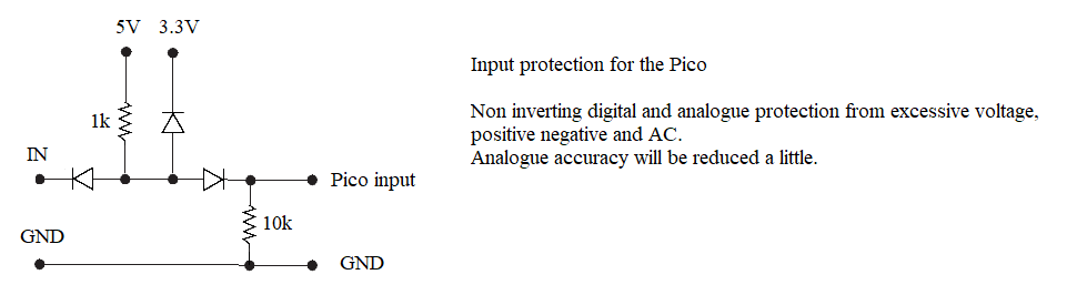 |
||||
| Mixtel90 Guru Joined: 05/10/2019 Location: United KingdomPosts: 8911 |
The problem with this sort of solution is when you see it in an industrial setting. Inputs are usually either 24V or off. Active low inputs are rare. They also have (to all intents and purposes) unlimited current capability (sometimes a 6A or even 10A HRC fuse) so the first thing after the input terminal should always be a resistor or varistor. The actual control voltage is often 24V AC straight off a control transformer, so is often somewhere between 20V and 30V depending on the mains at the time. Better quality gear might have a 24V DC supply block of some sort, but they aren't often used unless really necessary as they add to the cost and maintenance problems. They are usually pretty basic transformer-rectifier. If you are lucky there'll be a working reservoir cap so that the relays don't buzz too much! SMPS supplies are more common than they used to be, but they also add to the price of the panel (industrial DIN rail mounting SMPS supplies are often expensive). When the gear is in a generating station or somewhere like that there will be a station battery. This is kept on a float charge so (most) will be about 32V most of the time, falling to 24V and sometimes lower during a mains failure. The generator(s) will usually restore the charging supply once they come on line. It'll be a pretty noisy supply. Industrial control is a world of its own. :) You use 20A switch contacts to light an indicator lamp and switch a 100mA relay coil just because they are standard parts. :) This playtime PLC doesn't fulfill half the standards that you really need industrially. It needs power supply filtering (both as protection for the board and to prevent it radiating RF), better mains separation (e.g. slots between ELV and LV sides), relay contact suppression, input protection on *everything* and fully touch-proofing on all the output side, including underneath the PCB. For an experimenter's toy it's ok if they don't use more than 24V anywhere and definitely don't switch mains. Mick Zilog Inside! nascom.info for Nascom & Gemini Preliminary MMBasic docs & my PCB designs |
||||
| The Back Shed's forum code is written, and hosted, in Australia. | © JAQ Software 2026 |
