
|
|
Forum Index : Microcontroller and PC projects : Dead ground pin on picomite
| Author | Message | ||||
| lizby Guru Joined: 17/05/2016 Location: United StatesPosts: 3784 |
I have one picomite on which a single 0V pin doesn't work. I can't say for certain that it did previously, but I assume it did. I found out when I plugged it into a PCB I made; it runs to an RJ45 jack and through cat5 to another pcb where it plugs into a Chinese 6-relay module (and another PCB with 5.5mm x 2.1mm PCB-mount jacks connects to the relays). The picomite is powered by USB. The relays switch 9.5vac. When I tried it, the relays didn't work. I traced it to this 0V pin not working. I plugged another PicoMite into my PCB and everything works fine. Other than that, the faulty Pico seems fine. Since a new pico works perfectly, I'm not inclined to think that having had it in this circuit caused the problem, but that's certainly possible. It had been in other circuits, but I might not have been using that pin. What might cause a 0V to stop working? It doesn't appear to be the solder joint to the pin header--still no connection if I put my DVM on the castellated pad. Examining it with a magnifying glass doesn't reveal anything. I'll admit I don't handle these devices with care. ~ Edited 2022-08-02 03:51 by lizby PicoMite, Armmite F4, SensorKits, MMBasic Hardware, Games, etc. on FOTS |
||||
| pwillard Guru Joined: 07/06/2022 Location: United StatesPosts: 341 |
Odd. Each GND pin appears to have at least 3 connection points to the GND plane to thermally isolated pads. To have a GND pin not work... at least 3 traces on the PCB would have to fail (etched poorly even?) (or have been accidentally used as "fusible links"). |
||||
| Mixtel90 Guru Joined: 05/10/2019 Location: United KingdomPosts: 8911 |
Drawing too much current through it and popping the track? I always try to ground as many of the GND pins as possible so that current through them is evenly distributed (and no heavy current flows through the PicoMite pins at all). It also reduces noise on the GP pins. Edited 2022-08-02 04:31 by Mixtel90 Mick Zilog Inside! nascom.info for Nascom & Gemini Preliminary MMBasic docs & my PCB designs |
||||
| circuit Guru Joined: 10/01/2016 Location: United KingdomPosts: 305 |
Might we enquire what you were using this ground pin for? Was this a ground return for the relays? Have the relays got diode protection? I presume that the relays are on a driver board, but does the board have its own ground return or are you using the failed pin as a shared ground return for the relay coils? ...or for that matter, as a ground return for whatever the relays are switching? |
||||
| Sasquatch Guru Joined: 08/05/2020 Location: United StatesPosts: 385 |
Interestingly, the RP2040 IC has no "Ground Pins" as such. All ground connections are made to the big thermal pad on the underside of the IC package. So likely you have a defective Pi Pico Board or you burned out a PCB trace as @Mixtel90 suggests. Regards, -Carl |
||||
| Justplayin Guru Joined: 31/01/2014 Location: United StatesPosts: 330 |
Have you attempted to resolder the pin on the Pico board. It might simply be a bad solder joint. --Curtis I am not a Mad Scientist... It makes me happy inventing new ways to take over the world!! |
||||
| lizby Guru Joined: 17/05/2016 Location: United StatesPosts: 3784 |
Here is the 6x relay I'm using (it accepts a high turnon):  Module Module I haven't specifically traced the circuit, but it appears to have inline SMD resistors marked "102", so 1K. The ground is a return for the opto-couplers which turn on the relays. There's only one ground to the relay input screw terminal, marked DC-. With 3V3 to the pin marked DC+, the relays wouldn't switch. I connected 5V from the PicoMite, and they did switch, and the PicoMite output pins never show more than 3V3. On my PCB, I connected only the single GND pin to the RJ45 + CAT5 link to the relays, so it's possible that with all of the relays turned on, it burned out the pin--but, the second picomite I plugged in has worked with all relays turned on (though only briefly). I will run wires from additional GND pins to the RJ45 pin (and will probably make another pass on the Picomite PCB to connect additional GND pins). Here's a youtube video of it working in an enclosure: 6 relays Code: dim integer i,j,k,p(6)=(0,21,22,24,25,26,27) for i=1 to 6: setpin p(i),dout: next do: for i=1 to 6:pin(p(i))=1-pin(p(i)): pause 200: next: loop Ultimately what will be switched will be 24VAC to control bigger relays. I didn't have 24VAC so this is 9VAC, which works to light 12V LEDs. ~ Edited 2022-08-02 10:25 by lizby PicoMite, Armmite F4, SensorKits, MMBasic Hardware, Games, etc. on FOTS |
||||
| phil99 Guru Joined: 11/02/2018 Location: AustraliaPosts: 3291 |
As Lizby has measured directly between Pico pads it can only be faulty tracks. If it has only been powered by USB it is unlikely to be due to excessive current. Even a 3A USB supply will shutdown before the tracks blow. Lack of diodes on the relays would produce a voltage spike on the drivers but not a current pulse at the Pico. Just a manufacturing defect is left. Edit. Lizby's last post appeared while I was writing. That module not only has the diodes it also has opto-isolators on the inputs. The combined current of all the coils would still be way too low to fuse tracks. Edited 2022-08-02 10:18 by phil99 |
||||
| lizby Guru Joined: 17/05/2016 Location: United StatesPosts: 3784 |
Here's the relay module plus RJ45 PCB plus 6x 5.5mm x 2.1mm power jack PCB in a box. The CCTV plug on the left is for the 24VAC. 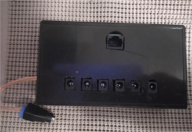 I'd never make a living as a machinist. Fortunately, I don't have to. PicoMite, Armmite F4, SensorKits, MMBasic Hardware, Games, etc. on FOTS |
||||
| Mixtel90 Guru Joined: 05/10/2019 Location: United KingdomPosts: 8911 |
Having seen the module I don't think this is an overcurrent on the GND pin. Even if the opto couplers were running with 20mA inputs (they are nowhere near that) that's still only 120mA - well within a GND pin capabilities. More likely to be a badly soldered pin on the PicoMite (or its socket). It can happen occasionally. The joint *looks* ok, but there's no connection to the track. Just rework the joint with either some flux or a bit of fresh solder. I'm not sure what the PicoMite is plugged into, but if it's a breadboard suspect that - some of them have terrible contacts and the usual male headers on PicoMites break them after only a couple of uses. Mick Zilog Inside! nascom.info for Nascom & Gemini Preliminary MMBasic docs & my PCB designs |
||||
| lizby Guru Joined: 17/05/2016 Location: United StatesPosts: 3784 |
Here's what it's plugged into (also shown in the video):  Tested against the castellated part of the Pico module not just the pin or the solder joint, with the picomite unplugged from anything. So the problem appears to be on the module. Whether it existed before I plugged it into this board, I don't know--but I had used it before for something--it had an LCD setup in the OPTIONS. PicoMite, Armmite F4, SensorKits, MMBasic Hardware, Games, etc. on FOTS |
||||
bigmik Guru Joined: 20/06/2011 Location: AustraliaPosts: 2981 |
Hi All, Which PIN number is it Lizby? Mick Mick's uMite Stuff can be found >>> HERE (Kindly hosted by Dontronics) <<< |
||||
| lizby Guru Joined: 17/05/2016 Location: United StatesPosts: 3784 |
Pin 23 PicoMite, Armmite F4, SensorKits, MMBasic Hardware, Games, etc. on FOTS |
||||
| bigmik Guru Joined: 20/06/2011 Location: AustraliaPosts: 2981 |
Hi Lizby, All, I put one under the microscope to see where the connections to GND are and the top side just connects to 2 isolated/unconnected islands and the Bottom has 3 connections to the Main GND copper pour. See below, (apologies for the rough images I just took a photo from my Microscope screen) TOP  BOTTOM 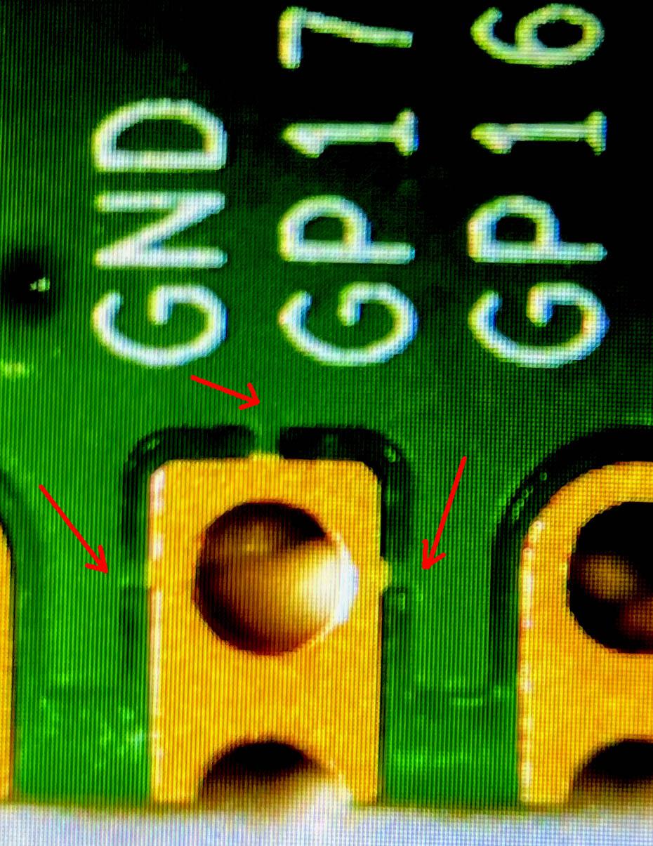 If you have a header pin soldered onto your Pico Pi then you will probably not be able to see the connections to the GND fill. Regards, Mick Mick's uMite Stuff can be found >>> HERE (Kindly hosted by Dontronics) <<< |
||||
| lizby Guru Joined: 17/05/2016 Location: United StatesPosts: 3784 |
Thanks, Mick. I've reworked the PCB to connect all the grounds. I'll wait a bit to see if I have other problems with different functions on this PCB--gotta keep JLCPCB busy. PicoMite, Armmite F4, SensorKits, MMBasic Hardware, Games, etc. on FOTS |
||||
| The Back Shed's forum code is written, and hosted, in Australia. | © JAQ Software 2026 |
