
|
|
Forum Index : Microcontroller and PC projects : Picomite Phase Correct PWM
| Page 1 of 2 |
|||||
| Author | Message | ||||
| Volhout Guru Joined: 05/03/2018 Location: NetherlandsPosts: 5927 |
Below text is meant to show what is possible with picomite. Things that are not directly implemented and documented in the user manual. May come in handy if it comes onto your path.... The picomite is a versatile platform that can be used for all sorts of things. In this case I use it as a pulse generator for driving a power convertor. Power convertors (switch mode power supplies) switch power MOSFET's or IGBT's at a frequency of 20kHz...1MHz in order to convert 1 voltage into another. There are literally zillions of power convertor designs but in my professions there is always need for one that does not exist yet. In that case you need to start from the basics (switching MOSFET's), design magnetics (transformer) and engineer the design to a product. In stead of starting out with a off-the-shelf driver IC, I decided to use the picomite (dual) PWM to generate the signals to drive the MOSFET's. Typically there are 2 that are drive out-of-phase (in other words 1 MOSFET is ON, the other OFF .... and vice versa). But MOSFET's are never allowed to be ON at the same time (when both are ON, they create a short circuit with excessive dissipation). So you need 2 signals that are out of phase, but need a "gap" between them to avoid MOSFET's being ON at the same time. In essence you can use a PWM and drive 2 outputs at different duty cycle. A PWM is essentialy a counter that starts at 0 and counts until it hit's the PWM comparator setting, and than toggles the pin. 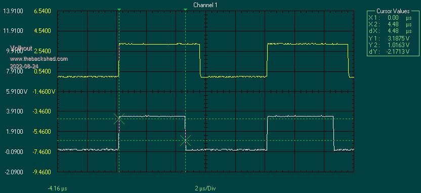 As you can see, both signals PWM0B top, PWM0A bottom have a different duty cycle, and this shows as a time gap (at the falling edge). The leading edge of both signals happens simultaneous. If you use these 2 signals to drive 2 MOSFET's the falling edges will be fine, but the rising edge (depending the speed of individual MOSFET's) both could still be conducting (briefly) at the same time. To create a symmetrical "gap" you need to change the PWM operating mode to "Phase Correct mode". The PMW counts from 0 upward until it hits the PWM compare value, toggles the pin, but at the end, it starts counting down again. Hitting the same value again, and toggles the pin again. It is easy to see that when counting up...and down... you need twice the time, so it is essential to double the PWM frequency when using phase correct mode. 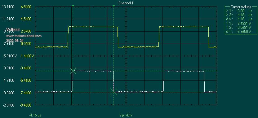 In this image you can see that there is a symmetrical "gap" between the 2 PWM outputs. You force the PWM into "Phase Correct" mode by setting bit 1 in the PWM control register. (see RP2040 manual). For PWM0 that is register &h40050000 Below code demonstrates the behaviour shown in above 2 graphs. SetPin gp0,pwm0a SetPin gp1,pwm0b Print "PWM0A/B running at 100kHz 45%/55% duty cycles, press any key to continue " PWM 0,100000,45,55 Poke word &h40050000,1 Do :Loop While Inkey$="" 'phase correct PWM (halves PWM frequency) Print "PWM0A/B running at 45%/55% duty cycle phase correct" PWM 0,200000,45,55 Poke word &h40050000,3 End Edited 2022-08-24 23:33 by Volhout PicomiteVGA PETSCII ROBOTS |
||||
| Solar Mike Guru Joined: 08/02/2015 Location: New ZealandPosts: 1211 |
Thanks for posting that information Volhout. What pwm duty cycle resolution do you have at 200Khz under basic? I have only used the PICO with micro-python using the PIO functionality to achieve deadtime gap between any 2 pwm outputs. Cheers Mike Edited 2022-08-25 10:07 by Solar Mike |
||||
| Volhout Guru Joined: 05/03/2018 Location: NetherlandsPosts: 5927 |
Acknowledging that the PWM runs at 62.5MHz maximum, you of coarse have limitations in frequency range and duty cycle range. But, different from off-the-shelf chips, you can play with them. In the end I think I will end up with a 62.5MHz/200=312kHz PWM, and as close as possible 49% and 51% duty cycle, but it could also end up in 48/52%. Many tests to be performed. Especially the EMI/EMC tests. I may even have to slow down the switching FET's to meet my target. This is for a "transformer driver" application (a high power version of the Texas Instruments SN6501). PicomiteVGA PETSCII ROBOTS |
||||
| robert.rozee Guru Joined: 31/12/2012 Location: New ZealandPosts: 2528 |
hi Volhout, that is a really neat hack, opening up a set of new and interesting applications for mmbasic  it also demonstrates nicely the usefulness of being able to directly 'tinker under the hood', experimenting with new ways to use the hardware and perhaps even suggest a path for future tweaks to mmbasic that can then expose the functionality directly via existing basic commands. Peter, Geoff: is this mode ("Phase Correct Mode") of operating the PWM something that could perhaps be added as an extension to the existing PWM command in mmbasic for the pico, and possibly also the MX170? for instance, using a negative frequency to specify the alternate mode? Geoff did build a 'tweaked' version of mmbasic for the MX170 that exposed direct access to setting the PWM count value here: http://www.thebackshed.com/forum/ViewTopic.php?TID=14558&P=2#182207 in that example a negative duty cycle parameter indicated a count value was being supplied rather than a duty cycle. later in the above linked thread the formula for the maximum (negative) value is given. in the case of the pico there would be a similar relatively simple formula for the number of 'ticks' within each cycle - in my case i just used trial-and-error to find the approximate limit, then worked backwards from there  cheers, rob :-) |
||||
| hitsware2 Guru Joined: 03/08/2019 Location: United StatesPosts: 738 |
..................******.......................******...................******.......... Gate 1 ******.......................******.....................******.......................*** Gate 2 � � � � � � Edited 2022-08-26 01:15 by hitsware2 my site |
||||
| Volhout Guru Joined: 05/03/2018 Location: NetherlandsPosts: 5927 |
Hi Hitsware, Yes, that is in my application (2x N-channel FET) needed, so I need an invertor for one signal, and a buffer for the other (the 3.3V pico cannot reliably drive anything other than a logic FET, so I will add buffers). But using 2 buffers (or 2 inverters) you can drive a P channel and N channel combo (half bridge). Beauty of the PWM is that "soft start" is simply a short basic algorithm controlling the PWM0A from 5% to 49% while controlling the PWM0B from 95% to 51%. Volhout Edited 2022-08-26 01:04 by Volhout PicomiteVGA PETSCII ROBOTS |
||||
| hitsware2 Guru Joined: 03/08/2019 Location: United StatesPosts: 738 |
Those standard PWM chips do what You want with few passives .... my site |
||||
| lizby Guru Joined: 17/05/2016 Location: United StatesPosts: 3782 |
For your soft start, are you looking at zero-crossing switching? Over what time period do you plan to accomplish this soft start--how many steps? Are you able to diagram what it would look like? I'm looking at the possibility of a soft start of a water pump from 120V AC from an inverter and 12V battery. (Not quite the scale of what you are doing.) PicoMite, Armmite F4, SensorKits, MMBasic Hardware, Games, etc. on FOTS |
||||
| hitsware2 Guru Joined: 03/08/2019 Location: United StatesPosts: 738 |
https://www.st.com/en/power-management/sg3524.html my site |
||||
| Volhout Guru Joined: 05/03/2018 Location: NetherlandsPosts: 5927 |
I am aware these exist, used the 3524 (almost 40 years ago) in an oscilloscope powersupply. The thread is about what you can do with a pico that is not obvious from current MMBasic. I will never build a professional power supply around MMBasic (firmware too much in flux, and not traceable and (to my knowledge) it is impossible to rebuild older versions (just in case you qualified your product with picomite release 5.07.01 a27). But tuning a convertors performance from the PC keyboard (terminal) is a lot easier than soldering timing resistors to a PWM chip. Edited 2022-08-26 03:41 by Volhout PicomiteVGA PETSCII ROBOTS |
||||
| Volhout Guru Joined: 05/03/2018 Location: NetherlandsPosts: 5927 |
Maybe it is better to add a 4'th parameter to the PWM command, that when not used keeps the standard mode. i.e. PWM frequency, duty cycle A, duty cycle B, "P" I have seen that many PWM's have this "phase correct" feature, so it could even become a standard extension of MMBasic. Volhout Edited 2022-08-26 03:47 by Volhout PicomiteVGA PETSCII ROBOTS |
||||
| JohnS Guru Joined: 18/11/2011 Location: United KingdomPosts: 4335 |
You could quite easily arrange that. Basically save all the stuff needed to build it (a VM image may be the easiest). Traceability etc is a pain but I'm sure you know that!! John |
||||
| robert.rozee Guru Joined: 31/12/2012 Location: New ZealandPosts: 2528 |
the downside with an extra parameter is that it requires additional complexity in the interpreter to decode it: distinguishing between a letter ("P") and a number, generating an error if it is the wrong letter, etc. in the case of the MX170 at least, there is almost no spare flash available for this sort of thing. a negative frequency, on the other hand, can be checked with just a couple of machine code instructions. then a couple or three more instructions to divide the frequency by -2, and a single poke to change the PWM configuration register. potentially it may only involve growing the firmware by a handful of bytes - a far smaller barrier when flash space is scarce. it also means the new feature can be 'silently slipped in' without needing to document it cheers, rob :-) |
||||
| Volhout Guru Joined: 05/03/2018 Location: NetherlandsPosts: 5927 |
Picomite does it all..... Thanks to the phase correct PWM the pico is designing (or tuning) this transformer driver circuit. Currently with 2x 2N2222A, but will change to 2 FET's once the shipment comes in. The picomite controls (PWM1) the load to the convertor (10mA...600mA) The picomite drives the 2 switching transistors with phase correct PWM0 The picomite measures input (ADC) and output voltage (ADC) The picomite measures the current through the switching transistors (ADC). The picomite does all the math to determine the efficiency of the convertor. Tomorrow I'll write the tuning algorithm to vary frequency, load, duty cycle, and determine the efficiency landscape (3d graph in excel from CSV data). Then the setup moves to the climatic chamber to see how things behave at different temperatures. Anyway, once the algorithm works, I can tune the transformer and FET's for best efficieny. The only thing I do not have automated yet is the input voltage. Which I may do using serial port. I must have a MAX232 somewhere. The pico can then also control the power supply. 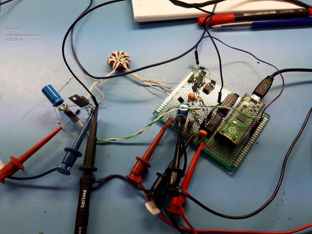 In case you wonder why the wire is so thick for 600mA: it is tripple insulated wire since the convertor must isolate input from output under 12kV surge. I will add surge protection at the switcher transistors. Edited 2022-08-30 01:13 by Volhout PicomiteVGA PETSCII ROBOTS |
||||
| phil99 Guru Joined: 11/02/2018 Location: AustraliaPosts: 3289 |
Combining the latest firmware with Volhout's expertise:- Symetrical + inverted PWM on any channel f2 = 2 * PWMfrequency PWA% = &H40050000 + &H14 * PWM_ChannelNumber 'Hex. address plus offset or - PWA% = 1074069504 + 20 * PWM_ChannelNumber 'Decimal address plus offset DY = Duty '(Percent) Poke word PWA%,3 PWM PWM_ChannelNumber, f2, DY, (DY - 100) 'eg > setpin GP4,pwm 'PWM ch 2 a > setpin GP5,pwm 'PWM ch 2 b > PWA% = &H40050000 + &H14 * 2 > f2 = 2 * 1000 'Hz > DY = 44 'pw% > Poke word PWA%,3 > pwm 2, f2, DY, (DY - 100) > _ |
||||
| matherp Guru Joined: 11/12/2012 Location: United KingdomPosts: 11499 |
This is an interesting and very timely thread as there is some undocumented functionality in 5.07.06 (was just something I wanted) that solves this problem another way. I'll describe this in another thread . Edited 2023-01-09 18:44 by matherp |
||||
| phil99 Guru Joined: 11/02/2018 Location: AustraliaPosts: 3289 |
Putting PWM SYNC to work. ' Stepper motor continuous drive SetPin gp0,pwm 'CH 0a SetPin gp1,pwm 'CH 0b SetPin gp2,pwm 'CH 1a SetPin gp3,pwm 'CH 1b PW = 25 'pulse width % F2 = 50 * 2 'frequency Hz Poke word &h40050000,3 Poke word &h40050014,3 PWM 0,F2,PW,PW-100,1 PWM 1,F2,PW-100,PW,1 PWM sync 0,50 ' Three phase motor drive SetPin gp0,pwm 'CH 0a SetPin gp1,pwm 'CH 0b SetPin gp2,pwm 'CH 1a SetPin gp3,pwm 'CH 1b SetPin gp4,pwm 'CH 2a SetPin gp5,pwm 'CH 2b PW = 100 / 3 'pulse width % F2 = 50 * 2 'frequency Hz Poke word &h40050000,3 Poke word &h40050014,3 Poke word &h40050028,3 PWM 0,F2,PW,PW-100,1 PWM 1,F2,PW-100,PW,1 PWM 2,F2,PW,PW-100,1 PWM sync 0,100/3,200/3 |
||||
| Volhout Guru Joined: 05/03/2018 Location: NetherlandsPosts: 5927 |
The combination of both features make for very simple code. Thank you for showing us! Volhout. PicomiteVGA PETSCII ROBOTS |
||||
| matherp Guru Joined: 11/12/2012 Location: United KingdomPosts: 11499 |
I'm being thick. Please explain what is happening in Phil's code that wouldn't be the case by eliminating the POKEs and running at F2=50 If this is doing something different I'll add the capability to the firmware for the next release. |
||||
| Volhout Guru Joined: 05/03/2018 Location: NetherlandsPosts: 5927 |
Hi Peter, Phill is using 6 outputs from 3 PWM's. The same can be done without the pokes, but then you would use 6 outputs from 6 PWM's. If you are free to choose your IO pins then both are equally beautifull solutions. It is not that the SYNC option is lacking something. It is more versatile because you can also sync up 2 totally different frequencies (i.e. 50Hz and 150Hz). And you need the sync in above example to line up the 3 PWM's. Phill tried that before with delays in the MMBasic program, but that was not very accurate. Regards, Volhout PicomiteVGA PETSCII ROBOTS |
||||
| Page 1 of 2 |
|||||
| The Back Shed's forum code is written, and hosted, in Australia. | © JAQ Software 2026 |
