
|
|
Forum Index : Microcontroller and PC projects : Intercepting signals via PICOMITE
| Page 1 of 3 |
|||||
| Author | Message | ||||
| electricat Senior Member Joined: 30/11/2020 Location: LithuaniaPosts: 299 |
Using logic analyser I reverse engineered custom LCD driven by HT1621. It would be easy task for any PIC microcontroller I am comfortable enough to decode such stream, but what about PicomiteVGA ? Was thinking attach in the middle to signals sent by microcontroller to HT1621. Read data, decode and send to �VGA screen using PicomiteVGA :) DATA is clocked out on rising edge of WR signal at every 1-2 uS . It is pack of 17 bits sent in 50 uS x 10 bursts totaling in about 1mS for all pack of LCD information. I failed read data using interrupts at 1uS rate with PicomiteVGA. It might easily be my incompetence in MMBASIC for PicomiteVGA of course. But is it technically possible deal with interrupts without jitters at 1uS rate at all ? 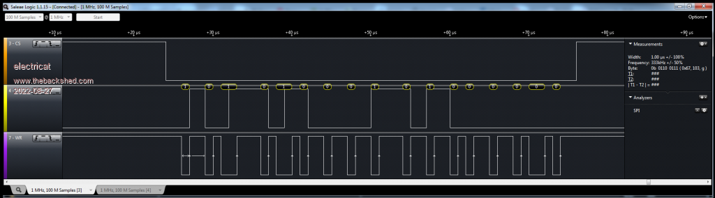 Edited 2022-08-27 19:17 by electricat My MMBasic 'sand box' |
||||
| JohnS Guru Joined: 18/11/2011 Location: United KingdomPosts: 4335 |
I think you'll need the bare minimum of code to have any chance and run the Pico with the highest clock you can. You might like to post your code in case people can suggest ways to speed it up. John |
||||
| electricat Senior Member Joined: 30/11/2020 Location: LithuaniaPosts: 299 |
This was my attempt to read data. I see interrupts are kicking in both CS and WR, but results are out of order. I should see for example something like BIN 101|000110|11111010 e.i. DEC 83706, but it looks like I catch only max 4 bits (out of 17 bits during 50 uS long CS) ! Dim bit_stream As integer receive=0 bit_ready=0 ' interrupt for CS signal Sub CS receive=Pin(gp22) ' check if CS is LOW or HIGH End Sub 'Interrupt for WR signal Sub WR bit_ready=1 ' FLAG as data is ready to read End Sub ' GP22 will be our CS SetPin GP22,DIN SetPin GP22,INTB,CS ' GP26 will be our clock line (WR) SetPin GP26,DIN SetPin GP26,INTH,WR ' GP27 will be DATA line SetPin GP27,DIN loop1: bit_stream=0 'wait for CS to became LOW, so it indicates data transfer begins Do While receive=1 Loop 'cycle read data while CS is LOW Do While receive=0 'wait for WR high transition to read DATA Do While bit_ready=0 Loop 'WR rises high, so now we can read data bit data_bit=Pin(gp27) ' read data bit bit_stream=bit_stream Or data_bit 'move data bit to variable bit_stream=bit_stream<<1 ' shift left for next data input cycle bit_ready=0 ' prepare for next data bit on high WR transition Loop Print bit_stream ' if at least something received, please show us DEC format, so we would convert it to BIN and see. GoTo loop1 My MMBasic 'sand box' |
||||
| matherp Guru Joined: 11/12/2012 Location: United KingdomPosts: 11499 |
No: interrupts are polled at the end of each Basic statement. There is no chance of doing what you want in Basic |
||||
| JohnS Guru Joined: 18/11/2011 Location: United KingdomPosts: 4335 |
Maybe stop using interrupts. They don't look to add anything except delays here. Also, you could overclock the Pico a lot. BTW I suspect the Print bit_stream will be (relatively) slow so with fast data would be a problem. No matter what you do, there will be a maximum you can't exceed. Try with slower data & see roughly where it is. John Edited 2022-08-27 23:09 by JohnS |
||||
| electricat Senior Member Joined: 30/11/2020 Location: LithuaniaPosts: 299 |
matherp, OK! :) Thx My MMBasic 'sand box' |
||||
| phil99 Guru Joined: 11/02/2018 Location: AustraliaPosts: 3289 |
Would this be of any use? https://www.thebackshed.com/forum/ViewTopic.php?TID=14475&PID=180443#180443#180443 I have found CSUB LOG to be very useful for catching fast data bursts. For repeatedly capturing data avoid using its Interrupt SUB, I cant seem to get out of it. Instead just wait for the receiving array to fill then process the data before the next batch arrives. |
||||
| Volhout Guru Joined: 05/03/2018 Location: NetherlandsPosts: 5930 |
The picomite executes basic commands at roughly 200000 per second. If you want to capture signals you need a minimum of 5 instructions. This limits your capture speed to around 10us. Anything faster is cannot be done in basic. A CSUB runs arm code and will be faster. The PIO in the rp2040 could be used, but will require pio code. Maybe there is some code on the internet. But what is your aim? Do you want to attach a VGA screen to a LCD to show the same picture or data? You did not mention, but in caae it is serial data you ccould capture it using the hardware SPI and maybe keep up with the speed Edited 2022-08-28 15:53 by Volhout PicomiteVGA PETSCII ROBOTS |
||||
| electricat Senior Member Joined: 30/11/2020 Location: LithuaniaPosts: 299 |
Yeah, CSUB and PIO looks good way to go. But I`m still not brave enough to move ARM ASM way. So much reading. Instead Microchip`s datasheets somehow warms up my heart every time I am looking through them. Found in dusty drawer PIC16F18855 and it seems to me this part will take interceptor role with no problem. � This is custom 7seg LCD I reverse engineered.  Wanted output data to something bigger and more eye and 3d printed case friendly :) 128x64 GLCD or 3d printed and LED backlighted LCD`s replica... or just old good 2x16 LCD... VGA screen seems be bit overkill but... how funny transition from damn small LCD it would be :) Edited 2022-08-29 03:33 by electricat My MMBasic 'sand box' |
||||
| Volhout Guru Joined: 05/03/2018 Location: NetherlandsPosts: 5930 |
Question remains, is it serial SPI ? If that is the case you could use the SPI input function in the picomite, and dump the data in an array. Then (at an easy pace) analyze the array and rebuild the 7 segment data. The SPI function know 8,16 and 32 bits. Not sure how to map 17 bits, but it is worth a try before you start writing C for the PIC. Option B: the display is controlled from a micro that reads 2 analog signals (voltage and current). Connect the voltage and current analog signal to the picomite GP26 and GP27 and you are set (appart from some ranging and calibration). Volhout Edited 2022-08-29 06:31 by Volhout PicomiteVGA PETSCII ROBOTS |
||||
| electricat Senior Member Joined: 30/11/2020 Location: LithuaniaPosts: 299 |
Volhout, Option B is too simple and easy. No FUN :) Also we would lose indication is it displaying source or output voltage (DC-DC "thing" has such function) My starting idea was 3D print like 100 x 70 mm size LCD display`s 7seg replica with added shifters and leds in backside. Option A also came to my restless head. Master who sends signals is n76e003at20. It`s 8051-based Microcontroller. And receiver, LCD driver HT1621B is low speed serial thing accepting 4-300khz. They did not used n76e003at20 hardware SPI pins either, but clearly serially bitbanging. And clock seems to be quite unstable 1-4 uS . Was not sure rp2040 hardware SPI would like this. But this was not a "stop" for me to try. After CS goes low they sent 17 bits of data in one go. First 3 bits for WR command, then 6 bits LCD`s RAM adress then 4+4 bits DATA. Then CS goes HIGH/LOW and next data part comes. Ok. I decided skip 3 first bits (they are of low importance) using CS interrupt and calculate time to wait and then read 16 bits. Or read 16 bits and ignore for a while 17-th just to see if PicomiteVGA hardware SPI would take on it. (I didn`t know picomite SPI function has 32 bits. manual says 4,8,16) So I tried :) But MMBASIC threw me "not all pins set for SPI". Tried different ways. Did not found error reason. Should be something stupid I miss. ' tried different combinations here as I was not sure if SETPIN GP28, GP27, GP26, ' SPI2 takes care on I/O prepare or no SetPin GP26,DIN SetPin GP28,DIN SetPin GP27,DOUT SETPIN GP28, GP27, GP26, SPI2 SPI OPEN 250000, 0, 16 OPTION LIST showed clearly- pins were free. Not connected to anything on my prototype PCB also. So I knew there might be possibilities: read forum/ask questions already answered once :) , reset, re-flash, change SPI channel/ pins or try to look at github sources (it helps sometimes, yes) etc... But I felt tired and I know PIC devices already, being close to hardware not difficult at all catch signal and decode. MMbasic running devices sure is nice and useful thingies. My MMBasic 'sand box' |
||||
| electricat Senior Member Joined: 30/11/2020 Location: LithuaniaPosts: 299 |
As by decision, I ended up using PIC`S hardware SPI in slave mode with CS independent line. After simple time synchronizing routine I`m starting read non stop bit to bit stream into 20 byte array. On interrupt each new byte reads from SSP2BUF and while SSP2ADD fills in with new bits, there is enough time for few simple interrupt routines. Used for task PIC18F24k22. Done. I can now do whatever I want as there is almost 500 uS time gap for sorting out received data and decoding things 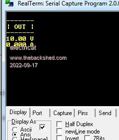 As far as I understand after studying manual, MMBASIC can`t do like this. You can read SPI but commanding like master=> slave, so it would never run under slaves clock ? Do I understand it correctly? I must read rp2040 datasheet and dive into problem deeper. PIO related reading seems to be interesting :) My MMBasic 'sand box' |
||||
| Mixtel90 Guru Joined: 05/10/2019 Location: United KingdomPosts: 8904 |
For SPI the slave never produces a clock at all. The master sends enough clock cycles for the slave to return all of its data. How much data has to be either a fixed amount or a figure sent by the slave as part of the comms protocol so the master knows how many clock cycles to send. What MMBasic appears to not be able to do is to act as a true SPI slave and only respond to a clock rather than producing it. There are SPI protocols where one or more devices can switch between master and slave, but it gets very knotted up because of the single clock source arrangement, which is fundamental to SPI because it's a truly synchronous protocol. Mick Zilog Inside! nascom.info for Nascom & Gemini Preliminary MMBasic docs & my PCB designs |
||||
| electricat Senior Member Joined: 30/11/2020 Location: LithuaniaPosts: 299 |
Yes, this is why I used PIC mcu for this task. But would it be useful to have such hw feature in MMBbasic then? :) My MMBasic 'sand box' |
||||
| Mixtel90 Guru Joined: 05/10/2019 Location: United KingdomPosts: 8904 |
IMHO yes. I've looked at using a multi-processor system and SPI is one of the fastest ways to transfer data. Unfortunately you can't use a PicoMite as a slave unless you write a slave routine. That's perfectly possible, I think, but I doubt if you could get a high enough speed to make it worth using SPI rather than multi-drop UART (which can be very fast). Also, SPI has no buffering under MMBasic, which is a bit of a limitation but not necessarily a game changer because of the synchronicity. Mick Zilog Inside! nascom.info for Nascom & Gemini Preliminary MMBasic docs & my PCB designs |
||||
| Tinine Guru Joined: 30/03/2016 Location: United KingdomPosts: 1646 |
Biting my tongue....well, keyboard fingers  SMH Craig |
||||
| matherp Guru Joined: 11/12/2012 Location: United KingdomPosts: 11499 |
Not possible in an interpreted language as the slave has no control over the data flow rates. No ability to clock stretch unlike I2C Edited 2022-09-17 19:12 by matherp |
||||
| Volhout Guru Joined: 05/03/2018 Location: NetherlandsPosts: 5930 |
You can do an SPI slave in PIO, but Peters comment remains true. You will loose data when you cannot pull it fast enough from the buffers. Only difference would be that the PIO is quadrupple buffered. So you would need to read it every 4 SPI transactions (8/16/32bits). That means that it may work in some applications, but there is definitely no guaranteed to work solution. If your PIC translates SPI into RS232 you may use it to get data in the UART buffers, and have a working system. Edited 2022-09-18 00:58 by Volhout PicomiteVGA PETSCII ROBOTS |
||||
| electricat Senior Member Joined: 30/11/2020 Location: LithuaniaPosts: 299 |
Volhout, Problem solved. I`m reading data from master bit to bit into array (array length is limited only by free ram) and can send to whatever I want. Oled, 16x2, 7seg or via spi to another device. So problem solved using PIC18f24k22 but not using PicomiteVGA. What was interesting for me as next step, would it be possible to implement slave SPI mode depended on masters clock into MMbasic. One like me could avoid of using one more part. I have in mind - hard coded as firmware in MMbasic, like SPI master or I2C master/slave are coded now. Sorry, english is not my native language and I`m usually not taking discussions in forums for reason as it is quite hard explain ideas, with bit limited enlish level. matherp says as I understant, this is the show stopper, not the interpreted language itself as such. What I wanted is, point to pic16f18875 datasheet: I made, just that. I am reading SSPxBUF register on every interrupt, while SSPxSR register fills in with new data. I have ~ 8 uS until another interrupt - more than enough time for only about 16 machine instructions I need to move data into array and 18f22k24 is`nt fastest thing either (if not double buffer/pair SSPxSR <=> SSPxBUF , I would not be able properly move buffer to array even with auto content saving interrupt. At least nothing better came to my poor cat`s head.) Now, I did not smoked under rp2040 datasheets, but could same principle be used with rp2040 too? If yes, up to some limited clock speeds (in my case I can read at least up to 400 Khz and did not made calculations how far more I could climb up) we should have time to read CS independent (!) stream (only using CLK and SDI). No? My MMBasic 'sand box' |
||||
| Mixtel90 Guru Joined: 05/10/2019 Location: United KingdomPosts: 8904 |
The problem is that a slave SPI has to see the clock edges in hardware - it's no use depending on software to do it as you can't be sure when they occur and the receiver is totally dependent on them because it's synchronous. A slave I2C device can pause the transfer by stretching the clock, but that can't happen under SPI as it has no control over the clock whatsoever. IMHO you *can* have a slave SPI on a PicoMite, but it will have to run slowly as the clock edges can only be detected using software interrupts which are only detected at the end of each line so the whole system has to take that into consideration. It does away with the point of using SPI. I2C would be a better choice even though it's slower or, if you want to be certain, a UART connection because you have big, automatic receive buffers and high baud rates under MMBasic. Mick Zilog Inside! nascom.info for Nascom & Gemini Preliminary MMBasic docs & my PCB designs |
||||
| Page 1 of 3 |
|||||
| The Back Shed's forum code is written, and hosted, in Australia. | © JAQ Software 2026 |
