
|
|
Forum Index : Microcontroller and PC projects : PicoMite Digital Signal Generator
| Author | Message | ||||
| Bleep Guru Joined: 09/01/2022 Location: United KingdomPosts: 806 |
I have re-worked some work done by Peter & Geoff from a few years ago. How to drive the AD9833 is a DDS function generator Geoff's DDS Signal Generator 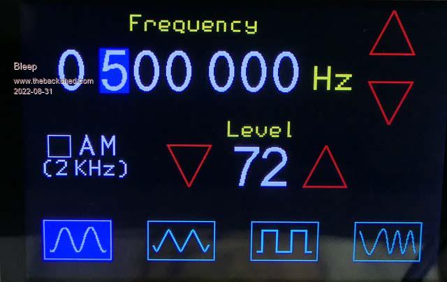 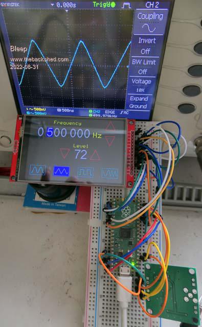 The main differences are that I am driving a 480x360 LCD touch screen (simply because I already had several I got cheap) so I had to re-size everything to make it look nice, I made the touch points larger than the buttons/display areas to make finger operation easier; I also had to change the way touch points were being handled, as they were using some form of interupt that isn't now required/supported on the PicoMite. I also found that for some reason, my setup, would only work when the SPI mode was 3, where as Peter originally used mode 2? Because the PicoMite has 2 SPI busses, I was able to get rid of a lot of SPI opening and closing as well :-) The wave forms it will produce, Sine, Triangle, Square, are very good up to at least 500KHz, after that the Triangle gets a bit rounded top & bottom, 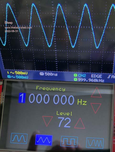 and the square goes a bit pear shape on the falling edge, 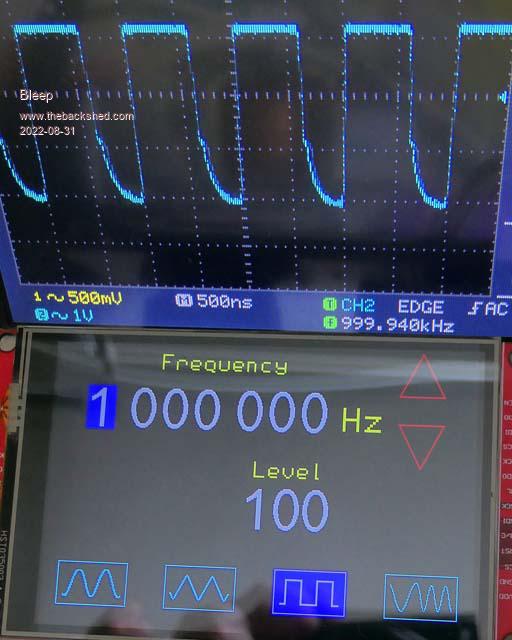 the sine is fairly good to 1MHz, above that it starts to get a bit squigly (technical term) probably because the DDS module only has a 25MHz clock, so at 5MHz sine wave output there are only 5 reference points to generate the sine and by the time you get to 10MHz there are only 2.5 sample point. 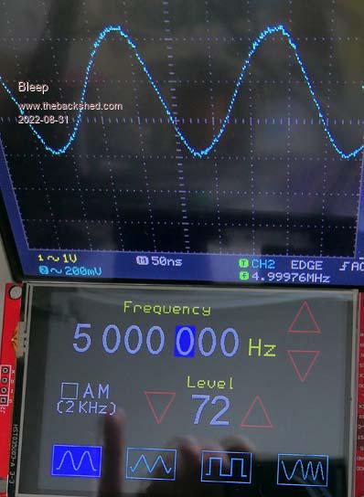 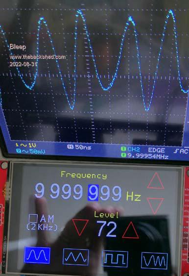 I attach my version of the MMBasic PicoMite code for your delectation. SigGenerator480x320.zip This is my Options setup. You must use a 480x320 touch screen and the OPTION CPUSPEED 126000 as some of the timings, particularly to do with the sweep waveform rely on it. 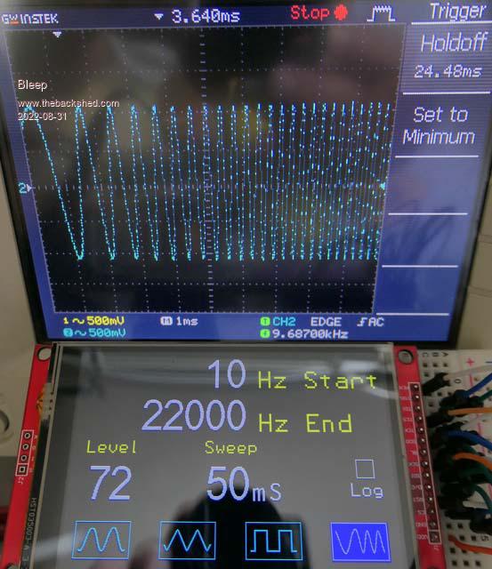 OPTION SYSTEM SPI GP10,GP11,GP12 OPTION SYSTEM I2C GP0,GP1 OPTION AUTORUN ON OPTION COLOURCODE ON OPTION CPUSPEED (KHz) 126000 OPTION DISPLAY 61, 195 OPTION LCDPANEL ILI9481IPS, RLANDSCAPE,GP19,GP18,GP17,GP6 OPTION TOUCH GP21,GP20 Next job is to put it in a nice box like the one Geoff used. :-) Regards, Kevin. |
||||
| Mixtel90 Guru Joined: 05/10/2019 Location: United KingdomPosts: 8904 |
I like this. :) Mick Zilog Inside! nascom.info for Nascom & Gemini Preliminary MMBasic docs & my PCB designs |
||||
| stanleyella Guru Joined: 25/06/2022 Location: United KingdomPosts: 2807 |
Wow! looks nice. |
||||
Grogster Admin Group Joined: 31/12/2012 Location: New ZealandPosts: 9975 |
Excellent work.  Could the issues you see on the waveforms be to do with a little bit of natural capacitance in your breadboard-type connections at those frequencies? It might behave better on a PCB layout with a good ground-plane. Perhaps. In any event, this is stellar work.  Smoke makes things work. When the smoke gets out, it stops! |
||||
| Volhout Guru Joined: 05/03/2018 Location: NetherlandsPosts: 5927 |
Hi, The distortion you see is most likely in the amplifier (or digital potmeter if that is used), not in the AD9833 itself. It should give a nice square wave and sine wave at 1MHz. Volhout PicomiteVGA PETSCII ROBOTS |
||||
| Bleep Guru Joined: 09/01/2022 Location: United KingdomPosts: 806 |
I have tried looking at the square wave signal direct, before the op-amp and it's the same, is it possible to look at it b4 the attenuator? I suspect that it's the usual cheap Chinese reject chip! Regards Kevin. |
||||
| The Back Shed's forum code is written, and hosted, in Australia. | © JAQ Software 2026 |
