
|
|
Forum Index : Microcontroller and PC projects : PM: 5" TFT dual-PM based PCB...
| Page 1 of 3 |
|||||
| Author | Message | ||||
Grogster Admin Group Joined: 31/12/2012 Location: New ZealandPosts: 9975 |
Hi all.  This is a board based loosely on the Explore-100 board, but using a couple of cheap PM modules due to the rarity of the E100 PIC32 chip these daze... 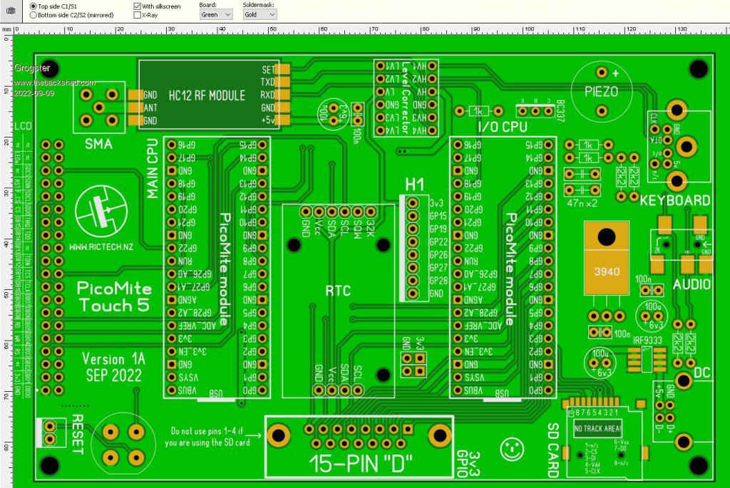 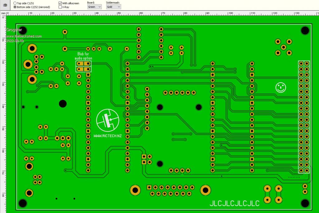 The main PM and the I/O PM are linked using COM2 on both modules. This allows you to write your own way of handling things from module-to-module, and the native COM port buffer can keep track of commands in both directions from or to either module, and you can just deal with anything inside your main loop. IRF9333 MOSFET for polarity protection was taken across from the E100 design, then I changed the DC input to a type-B USB socket, and so it becomes irrelevant due to the USB socket being idiot-proof, but I forgot to remove it before ordering some prototype boards. I will remove this SOIC for any future version of the PCB. Each PM module can have its own SD card. The main PM that controls the LCD and the touch, uses the SD socket on the LCD module, and the I/O PM module uses a uSD card socket. RTC module with I2C EPPROM chip, HC12 module for wireless connectivity, keyboard with level-corrector, piezo for beeps or touch click sound, 3.5mm stereo audio jack, and 15-pin "D" socket for the I/O PM pins. The D socket is placed so that you can still easily plug in the USB cable to each PM module to load the firmware etc. Board is same size as a standard 5" LCD module, that being 133mm x 84mm Once the boards arrive and I have built one, I will add more to this thread. In the meantime, feel free to comment on the 1A design - bearing in mind this is a prototype. It is unlikely I will be changing this design other then to fix any errors in the layout, but if someone suggests something really useful and easy to change or add.... Smoke makes things work. When the smoke gets out, it stops! |
||||
| Volhout Guru Joined: 05/03/2018 Location: NetherlandsPosts: 5927 |
Maybe you should adapt the analog audio output. The E100 circuit for the PIC does not work very well with the PWM output used by the picomite. You can take the circuit from Peters 1.7 board on the VGA picomite. I fail to see the second SD card slot. Edited 2022-09-09 22:01 by Volhout PicomiteVGA PETSCII ROBOTS |
||||
| matherp Guru Joined: 11/12/2012 Location: United KingdomPosts: 11499 |
Grogster Something I now do that makes life much easier is to include the OPTION settings on the PCB silkscreen then the board becomes largely self-documenting |
||||
| Grogster Admin Group Joined: 31/12/2012 Location: New ZealandPosts: 9975 |
This IS the LPF circuit from the PM manual, not the E100 one.  See page 28, PicoMite standard manual, or page 25 of the PicoMite VGA manual. This is what is on the board. Unless you were thinking of something else that is NOT in the manual perhaps? Do share a link if you are. Smoke makes things work. When the smoke gets out, it stops! |
||||
| Grogster Admin Group Joined: 31/12/2012 Location: New ZealandPosts: 9975 |
Good idea, I will include that for the 1B. Smoke makes things work. When the smoke gets out, it stops! |
||||
| matherp Guru Joined: 11/12/2012 Location: United KingdomPosts: 11499 |
That will be updated in the next manual 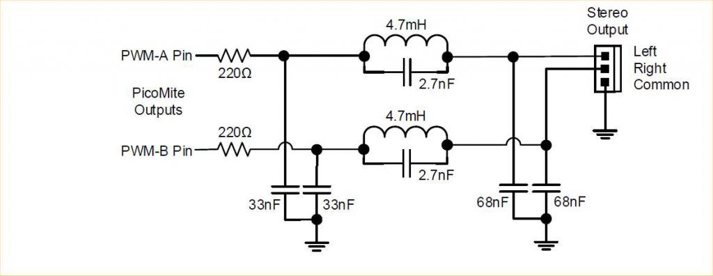 Note the inductor should have a 20ohm resistance e.g. B82144A2475J000 |
||||
| LouisG Senior Member Joined: 19/03/2016 Location: AustraliaPosts: 130 |
Very nice! How many analogue and counting pins come out on the D connector? . . . Louis |
||||
| Grogster Admin Group Joined: 31/12/2012 Location: New ZealandPosts: 9975 |
@ matherp & volhout - Oh, I see! �I have never seen that circuit. �Glad it will be in the new manual then. �I can find a way to incorporate that I think on 1B. @ LouisG - Pins GP0 to GP14 on the I/O PM module, are routed to pins 1-15 on the D connector. �Whatever those pins are capable of, the D socket can do. EDIT: I will make sure I label the D socket pins on the silkscreen in 1B also, along the same lines as Peter suggested with the OPTION commands. Edited 2022-09-09 22:19 by Grogster Smoke makes things work. When the smoke gets out, it stops! |
||||
| matherp Guru Joined: 11/12/2012 Location: United KingdomPosts: 11499 |
That means zero analogue pins - possible a mistake? |
||||
| pwillard Guru Joined: 07/06/2022 Location: United StatesPosts: 340 |
Can you add a 3 pin header for AUDIO as I have been waiting ~2 months for that SMD Audio jack from EBAY. (My order got canceled due to "out of stock" so had to order again, for the curious) Edited 2022-09-09 22:24 by pwillard |
||||
| Grogster Admin Group Joined: 31/12/2012 Location: New ZealandPosts: 9975 |
@ matherp - Zero on the D connector, correct. However, the three ADC pins(GP26, GP27 and GP28) can be accessed on the H1 header, along with ground and 3v3 references. @ pwillard - Yes, I think I can squeeze that into 1B also. Just for everyone's information, I will be releasing all the gerbers for this board, once I get it past prototype to prove everything essentially is working, so people can get the boards made themselves. I will also be offering them on my website, and PERHAPS a kit - not sure about that yet. Smoke makes things work. When the smoke gets out, it stops! |
||||
| Kabron Regular Member Joined: 30/11/2017 Location: GermanyPosts: 65 |
I guess 4 modules will be even better |
||||
| Volhout Guru Joined: 05/03/2018 Location: NetherlandsPosts: 5927 |
Some irony is good for the atmosphere on the forum, jokes also, but having 2 picomites on this board has a reason. The one driving the (parallel) SSD1963 has only few pins left. So you need something to expand IO to do anything usefull with the board (except looking the display). The choice to use COM2 for inter(pico)chip communication is logical. PicomiteVGA PETSCII ROBOTS |
||||
| vegipete Guru Joined: 29/01/2013 Location: CanadaPosts: 1179 |
No ground pin on the 15 pin D? Only the shell? Yikes. Visit Vegipete's *Mite Library for cool programs. |
||||
| Mixtel90 Guru Joined: 05/10/2019 Location: United KingdomPosts: 8904 |
My personal choice would have been for a boxed IDC male connector rather than the 15-pin D. They are cheaper and very easy to connect to using either a ribbon cable or female Dupont pins. The box gives some protection against shorts. Very much a matter of taste though. :) Mick Zilog Inside! nascom.info for Nascom & Gemini Preliminary MMBasic docs & my PCB designs |
||||
| Grogster Admin Group Joined: 31/12/2012 Location: New ZealandPosts: 9975 |
@ Kabron - Way to miss the point. Volhout's reply to your post sums it up perfectly. @ vegipete - No need for a ground pin there really. If you want a positive or ground reference, there are other places on the board such as header H1 or main system ground, and there is a 2x2 header with 3v3 and GND on it just above the D you can tap into, but I have used the shell for a ground on more then a few projects, and NEVER had a problem with doing that. Ever. I think the 'Yikes' comment is a little over the top, suggesting that it is fundamentally flawed to not have ground pins on the D. If I had put ONE ground on the D, someone would have moaned that there should have been two, or three, or 3v3's, or 5v's, or all of the above.....it never ends. @ Mixtel90 - I hear you, but see the above. The D socket choice was because I wanted and needed it that way. The D will not be changing to a box-header before anyone else asks. @ EVERYONE - I designed the board for my own purposes, not what everyone else wanted. Therefore, it has features that I want - but that perhaps many of the rest of you don't want.  I tried to make it flexible enough that others could use it which is why I posted this thread, but ultimately, at the end of the day, it was a design by me, for my purposes. I really hate design-by-committee, and it is one of the reasons I have pretty much not posted any new boards here in a long time, and probably the reason I won't ever do so again. Not that many of the ideas aren't good, but there is a reason that the term "Design by committee" exists(as a negative, BTW), and having had to deal with it many times now over many years.....I'm just done being nice about it anymore, that's all.  I'll leave it there. I'll leave it there.  Smoke makes things work. When the smoke gets out, it stops! |
||||
| Mixtel90 Guru Joined: 05/10/2019 Location: United KingdomPosts: 8904 |
No worries, Grogster, I fully understand what you mean. :) You can't please everyone and your design has to primarily fulfill your own purposes, no-one else's. The designs I publish are ones that I don't really have a personal purpose for, they are intended to be generic so design by committee doesn't bother me on them (usually). I do other designs as well, but they are for specific projects and won't see the light of day on here as there's no point. Thanks for showing us your design. It's useful to see how others approach things, even if the design doesn't apply to our particular purposes. We can all "pick holes", but those "holes" are usually there because the designer wants them to be for some reason. It's easy to criticize when you don't know *why* a particular arrangement has been used and we should bear that in mind. Mick Zilog Inside! nascom.info for Nascom & Gemini Preliminary MMBasic docs & my PCB designs |
||||
| pwillard Guru Joined: 07/06/2022 Location: United StatesPosts: 340 |
Geeze. I was not intending to sound like I was upset with you for sharing and the design not having a feature I would have added as if I had some sort of issue with your work. In fact, I was just mentioning my concerns due to the difficulties I've had finding that particular SMD Audio Jack. I really didn't mean to sound so critical that it prevents you from sharing. Sharing is good. Sharing gets us all in a frame of mind of "maybe we can do this too!". I hope we are not all sounding like a bunch of "GimmePigs" because that was certainly not *my* intention. Sorry for that as the FORUM does not do a good job of expressing our joy when we see something new in progress. Note: I also use Sprint Layout and love it when people share what they do with it. |
||||
| TrevorH Senior Member Joined: 06/04/2018 Location: United KingdomPosts: 145 |
Can I put my name on one when you have a working design, my efforts have fell on stony ground. I also haven't yet got my head round using 2 picos joined at the hip so to speak, has anyone done a description of how it works? |
||||
| Mixtel90 Guru Joined: 05/10/2019 Location: United KingdomPosts: 8904 |
The definitive source for the audio jack is, I think, RS Components in the UK. It looks like the one used for the CMM2: 3.5mm Stereo Socket. Switchcraft 35RASMT4BHNTRX (RS 705-1490, Mouser 502-35RASMT4BHNTRX) Mick Zilog Inside! nascom.info for Nascom & Gemini Preliminary MMBasic docs & my PCB designs |
||||
| Page 1 of 3 |
|||||
| The Back Shed's forum code is written, and hosted, in Australia. | © JAQ Software 2026 |
