
|
|
Forum Index : Microcontroller and PC projects : Sprint Layout 6.0
| Author | Message | ||||
| Mixtel90 Guru Joined: 05/10/2019 Location: United KingdomPosts: 5735 |
I just measure & draw components that don't already exist - switching to a 0.5mm (or finer) grid sometimes and using a digital calliper to get the sizes right. Either that or draw them from a manufacturer's drawing. After that I know they'll fit even if I don't do any printouts. You can draw components remarkably accurately in SL6 and, because you can save them, you only need to do it once. Mick Zilog Inside! nascom.info for Nascom & Gemini Preliminary MMBasic docs & my PCB designs |
||||
| matherp Guru Joined: 11/12/2012 Location: United KingdomPosts: 8592 |
Is there no way to import a dxf in Sprint with the board outline? That is what I can do with Designspark and seems like it should be a standard capability. |
||||
| Tinine Guru Joined: 30/03/2016 Location: United KingdomPosts: 1646 |
Yeah, I've been doing a lot of that because I have the PGA2040s and a 80-pin edge connector for the P2. Craig |
||||
| Mixtel90 Guru Joined: 05/10/2019 Location: United KingdomPosts: 5735 |
No, Peter. :( You can import a BMP of a board to trace over. That's the closest. Mick Zilog Inside! nascom.info for Nascom & Gemini Preliminary MMBasic docs & my PCB designs |
||||
| Rickard5 Guru Joined: 31/03/2022 Location: United StatesPosts: 328 |
OK Again Not the the Brightest Bulb in the box here but how do import all those Macros from Grogster ? I turned the volume on the monitor to max and could hear sound. Thanks Stanleyella |
||||
| Mixtel90 Guru Joined: 05/10/2019 Location: United KingdomPosts: 5735 |
Somewhere on your system you'll have the program directory called Layout60. Inside that there's a sub-directory called MAKROS. Inside that there's another called USER. I unpacked Grogster's files into a directory called Grogster in there. I also created my own directory under USER at the same time. It keeps stuff tidy. Note that changes to the files done like this don't take effect until SL6 is restarted so it's better not to do them while it's running. :) Edited 2022-09-26 23:33 by Mixtel90 Mick Zilog Inside! nascom.info for Nascom & Gemini Preliminary MMBasic docs & my PCB designs |
||||
| pwillard Senior Member Joined: 07/06/2022 Location: United StatesPosts: 274 |
One of the things I did with USER space was to create a macro library folder called "1st Choice" which is where I keep the really common shapes I use a lot. And yeah... I try to warn everyone that the default Header Shapes are too small for actual headers... �I screwed up a very expensive OSHPARK order with that mistake and that day I fixed ALL the header files to have 0.9 sized holes while grumbling about wasted money. One of the best things USA could do is also go metric IMHO. I've made PCB, CAD, and 3D MODELS in metric ONLY since 1999. I do the same with SPLAN 8, where common schematic symbols are in one place. Less common items are in their own related folders... like Switches, Headers, Regulators, Custom IC outlines... etc. Edited 2022-09-27 01:12 by pwillard |
||||
| Tinine Guru Joined: 30/03/2016 Location: United KingdomPosts: 1646 |
SL-6 buddies  I wonder if you'd be so kind as to share your DRC settings, please? I intend to use JLC-PCB and I've followed their spec' but it would be nice to compare with those who have already been through this process. I use Windows-Key + Shift + S to grab a screen clipping. Craig |
||||
| Mixtel90 Guru Joined: 05/10/2019 Location: United KingdomPosts: 5735 |
How right they are is anyone's guess, although I did do *some* research. :) Minimum Distance: Copper 0.15mm Drillings 0.50mm Min/Max: Drilling min 0.30mm Drilling max 8.00mm Track min 0.20mm Annular ring min 0.20mm Silkscreen min 0.01mm I've had text height as small as 1.1mm if it's in capitals, normal width and bold. I've also had track width down to 0.15mm. I don't get too upset about silkscreen on vias as they are usually small enough not to matter. For my pictures I usually use Export as JPG then crop them using PhotoFiltre. I can have all sorts of junk on screen then, but only post what I want to. Edited 2022-09-27 03:45 by Mixtel90 Mick Zilog Inside! nascom.info for Nascom & Gemini Preliminary MMBasic docs & my PCB designs |
||||
| Rickard5 Guru Joined: 31/03/2022 Location: United StatesPosts: 328 |
Thanks for the heads up on the headers I found that out the hard way with the Gemini/ Pico Pair board, Mixtel made some of the headers though holes too small and I had to turn some of the headers down some pins on my watchmakers lathe by .005" to fit in the holes. <rant> I've Retyped my Response 4 times to try to avoid being Banned so forgive me, but the 49 other lesser states my try to force Metic, but in my Shop Metric will Never Infect my FREEDOM UNITS! if GOD himself had intended is to measure things in Metric, Laroy S. Starrett would have made my tooling in Micky Mouse Measurements 100 + years ago, Having to use Metric with 3d Printing is the Bane of my Existence ! I turned the volume on the monitor to max and could hear sound. Thanks Stanleyella |
||||
| Mixtel90 Guru Joined: 05/10/2019 Location: United KingdomPosts: 5735 |
One of the perils of having 12 fingers and 16 toes I'm afraid, Rick. ;) I can't remember which holes now... It's a mistake I made some time ago but I;ve usually managed to catch it since! 0.72mm is fine for female SIP sockets but not for the male pins. Mick Zilog Inside! nascom.info for Nascom & Gemini Preliminary MMBasic docs & my PCB designs |
||||
| Volhout Guru Joined: 05/03/2018 Location: NetherlandsPosts: 3553 |
KICAD has a nice PI 3D symbol.... 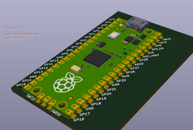 PicomiteVGA PETSCII ROBOTS |
||||
| Mixtel90 Guru Joined: 05/10/2019 Location: United KingdomPosts: 5735 |
I had a play with KiCAD some time ago. I thought it was very good to work with providing you didn't need to create new components. The hassle involved in that really put me off it. Even following (or trying to follow) the manual was a real chore for me as it deemed to assume that you already knew a lot about PCB design. Mick Zilog Inside! nascom.info for Nascom & Gemini Preliminary MMBasic docs & my PCB designs |
||||
| Rickard5 Guru Joined: 31/03/2022 Location: United StatesPosts: 328 |
12 fingers and 16 toes? I thought you were English not Welsh? it's not biggie it just gave me a chance to play with with my little watch maker's Lathe :) besides This is Hard I've tried absolutely Nothing and I'm all out of Ideas :) :) :) :) I turned the volume on the monitor to max and could hear sound. Thanks Stanleyella |
||||
| phil99 Guru Joined: 11/02/2018 Location: AustraliaPosts: 1793 |
Not having a Watch Maker's Lathe I just drill them. If it also acts as a via you must solder the top as well. For a header you must first bevel the base of the plastic at those pins with a craft knife so you can get a fine iron tip to the pin. Another trick is to drill those holes a little over size (or just wiggle the drill from side to side) and solder a strand of very thin wire (eg. from a bit of flex) through those holes (*) before inserting the header. If I have paid for a PCB I am going to b... well use it! (*) Poke the strand through from the top, fold it flat on the pad. then solder just that side of the pad, you don't want to cover the hole. Edited 2022-09-27 11:35 by phil99 |
||||
Grogster Admin Group Joined: 31/12/2012 Location: New ZealandPosts: 9066 |
@ Rickard5 - sorry I did not state how to "Install" my macro pack, but Mixtel90's post directly below your one is EXACTLY how to do it, so I won't repeat it here Yes, it's the simplicity factor that makes me love SL6 so much. That, and that it is very cheap/affordable vs other professional CAD costing several hundred dollars. While I have no illusions as to SL6's limits when compared to other software, it was it's simplicity and price that made me choose it, and while I know that PCB CAD software especially can be something of a hot debating point between people, yet again it came down to a case of: "If it works for you...." I have not YET found a need to go beyond four-layer boards, and am not really expecting to have to anytime soon, but that IS a limit of SL6, and they have told me in emails that they are never going to expand it to support six-layer or more. And for its price-point, that is fair enough too. Six-layer boards can be had at many PCB houses now including JLC, but the price is rather painful, so best to stick with no more then four-layer for as long as possible! ONE THING TO NOTE ABOUT SL6 - is that it CANNOT re-import its own Gerber files IF THE DESIGN USES A GROUND-PLANE. Importing those corrupts the import. It imports its own Gerbers without a GP just fine, or anyone else's Gerbers without a GP, but if you use a GP in your design, it is VITAL that you have backups of the LAY6 file, cos if you lose that, you can't recover from the exported Gerbers - the import is just a mess. SL6 developers are aware of this cos I emailed asking about it, but it is not considered a priority to fix, cos you are expected to ALWAYS have the LAY6 file on hand.(so, therefore, on non-urgent bug list) Golden rule from all of that, is make sure you have BACKUPS, especially of your lay6 files - but I don't need to tell the lovely technically savvy members here to have backups, now, do I?! (rhetorical)  Smoke makes things work. When the smoke gets out, it stops! |
||||
| Rickard5 Guru Joined: 31/03/2022 Location: United StatesPosts: 328 |
@Grogster I chose SL6 over all else because Mick recommended it and I think Lisby uses it , and there is such a Great Group of supportive people here willing to help, I've Learned more from this post than in messing with it for the last few weeks. I've been a HUGE Autodesk Guy since Autocadd 4, in fact I've used and still use Autocad 2002 and 3D STUDIO 9 SINCE 2000 AND REFUSE to upgrade simply because I paid almost $10k to legally own it for professional reasons, and now in 2022 I have 20+ years of experience using it. I still do side work, 3D Models and CNC drawings because it works and Fusion 360 is so "Feature Rich" is makes my head HURT BAD! Autodesk EAGLE is more of the same and SL6 lis the Br�derbund of PCB Design Software, But the documentation leaves lots to be desired, and the YouTube videos SUCK I have the non talking music videos I can't work along with! ThaNK YOU EVERYBODY FOR ALL YOUR HELP LOVE ALL You Guys but only in an imperial non metric way :) I turned the volume on the monitor to max and could hear sound. Thanks Stanleyella |
||||
| Rickard5 Guru Joined: 31/03/2022 Location: United StatesPosts: 328 |
This little lathe mill isn't very accurate or stout, but it's cheap and serviceable for small hobby stuff like little desktop robotics, I've seen other guys using the even lower cost ones at robot contests I got a small Bonus coming and as soon as it get's here I'm getting one of these to cut PCBs Edited 2022-09-27 13:17 by Rickard5 I turned the volume on the monitor to max and could hear sound. Thanks Stanleyella |
||||
| Tinine Guru Joined: 30/03/2016 Location: United KingdomPosts: 1646 |
No Kidding  My routine is to: 1)have Auto-backup enabled 2)Re-name the file each day 3)Throughout the day, use "Copy Board" 4)Have the folder sync'd to DropBox Craig |
||||
