
|
|
Forum Index : Microcontroller and PC projects : ILI9488 MISO Fault Question
| Page 1 of 2 |
|||||
| Author | Message | ||||
DrifterNL Regular Member Joined: 27/09/2018 Location: NetherlandsPosts: 56 |
Reading about the ILI9488 MISO fault in which the MISO doesn't go into tristate and thus the SPI can't be shared unless the LCD MISO is disconnected, I wonder if a buffer could be placed between the MISO and connection controlled by the LCD CS line. It seems to me to be a solution to getting an ILI9488 operating correctly and fully functional while sharing the SPI bus with other devices (sd card) but I could be over looking something. Anybody ever try this? Something like this ? Floating Point Keeps Sinking Me! Back To Integer So I Don't Get Injured. |
||||
| matherp Guru Joined: 11/12/2012 Location: United KingdomPosts: 8567 |
680 ohm resistor in the ILI9488 MISO line normally works. Else it can be done with a single transistor. Someone posted the transistor circuit recently and hopefully they will chime in |
||||
| phil99 Guru Joined: 11/02/2018 Location: AustraliaPosts: 1773 |
Here it is. https://www.thebackshed.com/forum/ViewTopic.php?TID=11419&P=3#191429 The transistor only connects LCD_SDO to MISO when LCD_CS is pulled low. Most people find just the resistor is enough but I found SD card access unreliable. |
||||
| DrifterNL Regular Member Joined: 27/09/2018 Location: NetherlandsPosts: 56 |
Thanks for the info. I'll give it a look. Floating Point Keeps Sinking Me! Back To Integer So I Don't Get Injured. |
||||
| DrifterNL Regular Member Joined: 27/09/2018 Location: NetherlandsPosts: 56 |
I gave it a try but with an BC557 transistor and 4K7 resistor. Testing with blit read, blit write, checking colours with pixel, reading from and writing to SD card all seems to work.  Edit: After further testing the bc557 with 4k7 resistor doesn't work. The colour code is read back incorrectly, every lsb is read back as 0. example: Clearing the screen with rgb(blue) and reading the colour code back with pixel returns 254 instead of 255 etcetera. oh well.. Edited 2022-10-17 10:07 by DrifterNL Floating Point Keeps Sinking Me! Back To Integer So I Don't Get Injured. |
||||
| phil99 Guru Joined: 11/02/2018 Location: AustraliaPosts: 1773 |
4k7 may be too low, try values from 10k to 33k. 33k works with a PN200. Also the BC557 might not have enough reverse gain, try swapping C and E. The Pico pin capacitance needs to be rapidly charged and discharged requiring some gain in both directions. To test the reverse gain of the BC557 connect the collector to 3.3V with emitter to ground via 1k and base to ground via 56k. That will give a base current of about 50uA and the millivolts across the 1k will give the C/E current in uA. Divide that by 50. The PN200 had a reverse current gain of about 30. If it's gain is too low and you can't get a PN200 try two BC557s in reverse parallel (C to E, E to C). Each with its own 33k base resistor to LCD_CS Edit. Doh, The light just went on! MMBasic uses 16 bits for LCD screens, not 24 bits. You will never get 255 back for any colour. Your transistor is probably working just fine. Edited 2022-10-17 17:26 by phil99 |
||||
| DrifterNL Regular Member Joined: 27/09/2018 Location: NetherlandsPosts: 56 |
Now I remember reading that somewhere also... oops But something isn't adding up so I tried something: I disconnected the SD card MISO line and reconnected the lcd MISO directly to the PicoMite. If this is 16 bit (5-6-5) colour then if I cls 263172 (&b00000100 00000100 00000100) I should read back with pixel value 1024 but I get value 263172 which seems that this is an 18 bit (6-6-6) colour. looks like MMBasic drives the ILI9488 in reduced 262K 18bit (6-6-6) colour mode. I reconnected the sd card reader and built up the transistor circuit again but was still not getting the correct values with 5K1, 10K, 20K, the error just went up. I Then went down in resistance and tried an 2K2 resistor and it worked! Reading and writing from to sd card and Blit works and pixel gives the correct 18 bit colour code I will do some further testing but it looks like the BC557A with a 2K2 resistor works. Edited 2022-10-18 11:01 by DrifterNL Floating Point Keeps Sinking Me! Back To Integer So I Don't Get Injured. |
||||
| phil99 Guru Joined: 11/02/2018 Location: AustraliaPosts: 1773 |
That is all useful information. That the BC557 needs such a low value base resistor suggests that it is marginal in this application, but if it works it will do. I suspect that it isn't acting as a transistor at all in the reverse direction, but the two junctions are making a "Double Diode Switch". Before decent high frequency transistors were available a pair of diodes could be used to switch video and VHF signals. When the diodes are reverse biased it is off and pass the signal when they have sufficient forward bias. Edit 27/10 Tested a pair of diodes and and SD card, Blit, Save Image and Pixel() all work properly. Have tested with resistor values from 1k8 to 10k. A pullup from MCU MISO to 3V3 could be added if needed. 5 to 10 times the CS resistor value. 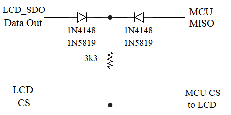 Counting the colours on an ILI9488. It is indeed RGB 666 > p=0 :b=0 :for n=0 to 255 : pixel 9, 9, n :p= pixel(9,9):if p=n then :inc b :endif :next : ? b;" Blues" 64 Blues > p=0 :g=0 :for n=0 to 255 : pixel 9, 9, n<<8 :p= pixel(9,9):if p=n<<8 then :inc g :endif :next : ? g;" Greens" 64 Greens > p=0 :r=0 :for n=0 to 255 : pixel 9, 9, n<<16 :p= pixel(9,9):if p=n<<16 then :inc r :endif :next : ? r;" Reds" 64 Reds > ? 2^6 64 Edited 2022-10-27 22:01 by phil99 |
||||
| DrifterNL Regular Member Joined: 27/09/2018 Location: NetherlandsPosts: 56 |
After rearranging / cleaning up my breadboard, which involved moving the transistor circuit and using shorter jumpers, it failed again. I turned the BC557 around, e to c and c to e, and it worked again. Looks like the BC557 was just working and any changes meant having to change and test the circuit again. I didn't want to deal with this anymore and so I ordered a hand full of PN200 transistors, which should come in any day now, and have the correct value resistors on hand. Oh, I totally missed your updated post with the diodes.... Thanks for confirming RGB 6-6-6 colour code. Edited 2022-11-03 03:29 by DrifterNL Floating Point Keeps Sinking Me! Back To Integer So I Don't Get Injured. |
||||
| phil99 Guru Joined: 11/02/2018 Location: AustraliaPosts: 1773 |
Decided to see if the BC557 could be made it work reliably. The closest I have is a BC558 and it too needed a very low value base resistor. As the chip problem is that SDO is active low when it should be off a diode with anode to SDO was added as per the diagram. Tested with Pixel (above colour counters return 64 each for R, G & B), Blit, Files, Load Image and Save Image. Using the "Remove Bits Till it Fails" design philosophy the Diode Switch passed all the above tests with just one diode. 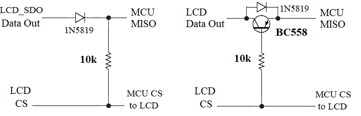 PS Touch also works. Edited 2022-11-21 22:10 by phil99 Footnote added 2024-04-15 12:11 by phil99 The 4" IPS ILI9488 is different to the panel above. The resistors near the SD socket are 4.7k pull-ups. R8 on SDO must be removed if the SD card is sharing SPI with the LCD panel. Otherwise the 10k (can be 4.7k to 10k) is unable to pass SDO to MISO. You can use other diodes provided they have sufficient junction capacitance. eg 1N400x series rectifiers work but 1N914 and 1N4148 don't unless you add 22pF to 150pF in parallel. |
||||
| stanleyella Guru Joined: 25/06/2022 Location: United KingdomPosts: 1639 |
the ili 9341 amd ili 9488 have the same pins. ili9341 all works. ili9488 graphics works but connecting touch and calibrate did get to 2 checks but failed, now it fails after first test. yawn. I will stick to ili9341 which works.... and 320x240 is more normal. pity, 9488 does graphics ok |
||||
| DrifterNL Regular Member Joined: 27/09/2018 Location: NetherlandsPosts: 56 |
My PN200 transistors came in and I tried the circuit. It was still not working until I changed around the emitter and collector and all seems to work now. The SD card, touch and Blit works as well as pixel. Maybe I got stand-in / fake PN200s? The circuit with the diode and resistor also looks like something to try. Floating Point Keeps Sinking Me! Back To Integer So I Don't Get Injured. |
||||
| stanleyella Guru Joined: 25/06/2022 Location: United KingdomPosts: 1639 |
I tried the circuit https://www.thebackshed.com/forum/uploads/phil99/2022-11-21_155644_ILI9488%20MISO%20Fault%20Fixer-2.png But got to try in5819,so order, schottky, low voltage drop. best I get with a in4001 was all four test points working but bad calibration problem. from there it is two tests work then calibration error. display works fine. |
||||
| phil99 Guru Joined: 11/02/2018 Location: AustraliaPosts: 1773 |
Tested it with 1n4007, 1n914, 1n4148 and resistors from 3k3 to 10k. All work with this test program. https://www.thebackshed.com/forum/ViewTopic.php?FID=16&TID=11419&LastEntry=Y#194465#194465 Perhaps the touch chip was damaged if you connected it without a resistor or diode in series with LCD_SDO. When idle it is active low so when the touch T_DO goes high it is driving in to a very low resistance (about 40 ohms). To test this remove the diode and resistor and leave LCD_SDO unconnected. Then try to calibrate touch. If touch won't work with nothing else sharing MISO it may be damaged. |
||||
| stanleyella Guru Joined: 25/06/2022 Location: United KingdomPosts: 1639 |
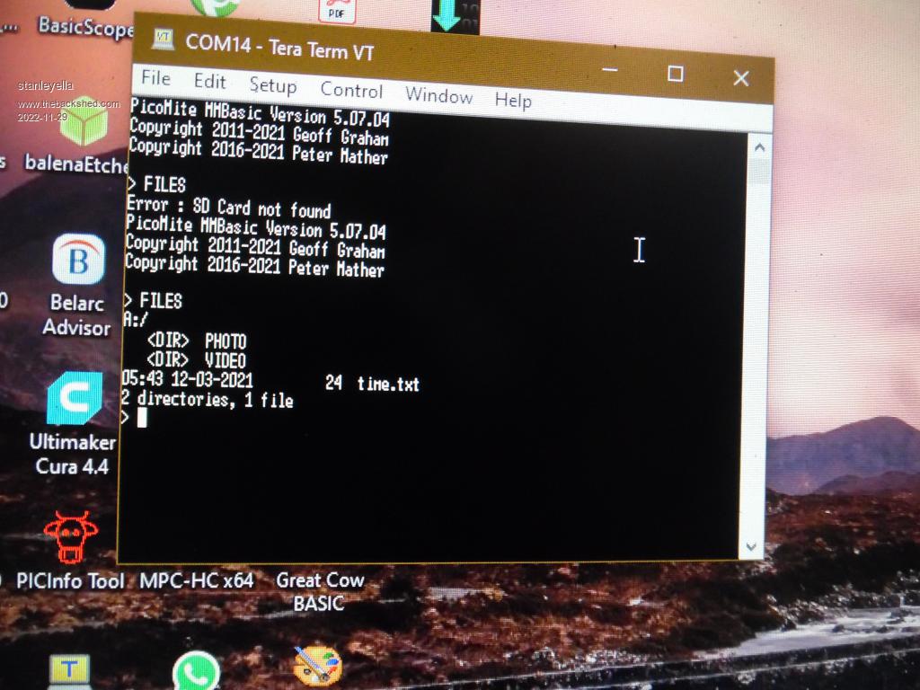 removed the diode and 10k and disconnected lcd miso then touch do and it did the gui calibrate and test??? weird. it is not to supposed to work. 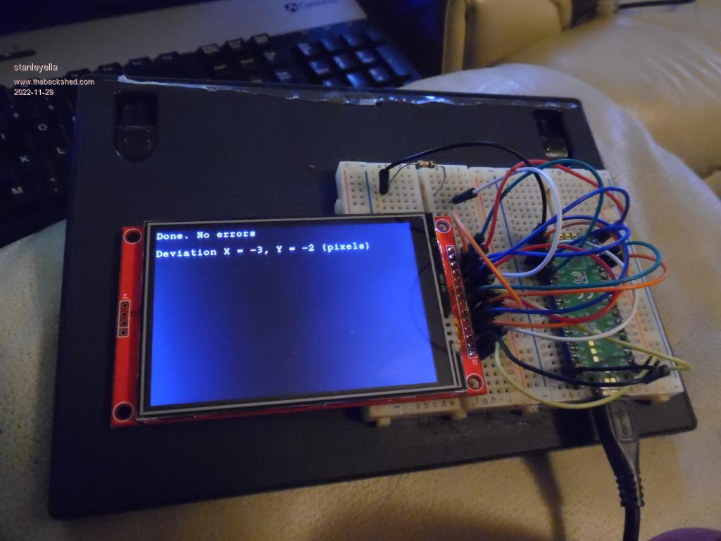 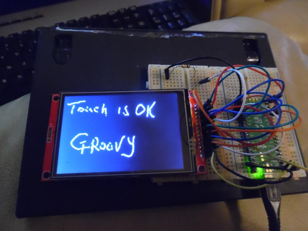 Edited 2022-11-29 04:01 by stanleyella |
||||
| stanleyella Guru Joined: 25/06/2022 Location: United KingdomPosts: 1639 |
Hi phill99. I appreciate your replies. The ili9488 seems ok when it should have problems. odd Tried a blit program and it now fails. Does not blit. Is this relevant? I knew too good to be true. |
||||
| stanleyella Guru Joined: 25/06/2022 Location: United KingdomPosts: 1639 |
Hi phill99. I appreciate your replies. The ili9488 seems ok when it should have problems. odd Tried a blit program and it now fails. Does not blit. Is this relevant? I knew too good to be true. |
||||
| phil99 Guru Joined: 11/02/2018 Location: AustraliaPosts: 1773 |
Ok that proves the touch chip has not been damaged, it was just interference from LCD_SDO preventing touch working. Blit, Pixel() and Save Image cannot work while LCD_SDO is disconnected. That is the pin that sends data from the screen to the Pico. The problem is three outputs (LCD_SDO, T_DO & SD_DO) must share one input (MISO). For that to work only one can be active at a time, and the faulty LCD_SDO is always active. The reason for the 680R or transistor or diode circuits is to provide enough isolation from LCD_SDO to allow touch and SD to work but still allow LCD_SDO to access MISO. Perhaps the fault on your panel is different. Measure the voltage between LCD_SDO and Gnd. (with nothing else connected to that pin) and let me know what it is. Mine is close to 0V. How the diode switching is supposed to work:- With LCD_SDO low and LCD_CS high the diode is reverse biased, isolating LCD_SDO from MISO so touch or SD should be able to send data to MISO. When the Pico wants data from the screen the Pico pulls LCD_CS low (the other two CS pins are high keeping Touch and SD off). This allows the diode to be forward biased so LCD_SDO can send data to MISO. When screen data sends LCD_SDO high (and LCD_CS is low) it goes through the diode to MISO. When screen data sends LCD_SDO low (and LCD_CS is low) the resistor pulls MISO low. . Edited 2022-11-29 17:33 by phil99 |
||||
| stanleyella Guru Joined: 25/06/2022 Location: United KingdomPosts: 1639 |
great info but same problems but only tried 680R and the diode/10KR It is either graphics including blit but no touch or working touch, sd card and graphics but no blit... which I had never thought would be affected. If I can not get it to work like ili9341 then do I need blit? would gui dials be affected? I can not get it to do blit even after option reset and resetting everything, what an interesting display. Not boring like ili9341 which works. Edited 2022-11-30 09:32 by stanleyella |
||||
| phil99 Guru Joined: 11/02/2018 Location: AustraliaPosts: 1773 |
Blit, Pixel() and Save Image all need to read data from the screen and thus need SDO (Serial Data Out). The 680R only provide partial isolation but everyone else has found it good enough to get touch working as the touch chip can easily supply the 4.5mA that the 680R draws. SD cards can be a bit fussier, so some form of switch is needed to turn SDO off when the SD card is in use. Are you certain all the breadboard connections are perfect? No one else is having this much trouble. Try the transistor one here. https://www.thebackshed.com/forum/ViewTopic.php?FID=16&TID=15214&LastEntry=Y#194594#194371 I will experiment with other methods. Edit Other Methods. Both of these pass all tests. Just about all normal optocouplers should be ok. 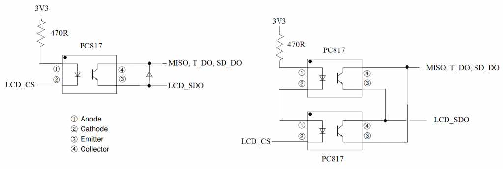 Otherwise I can come over and have a look at it. Just send the airfare, business class will be adequate. . Edited 2022-11-30 17:45 by phil99 |
||||
| Page 1 of 2 |
|||||
