
|
|
Forum Index : Microcontroller and PC projects : PIC/Mikromite/ADC reading
| Page 1 of 2 |
|||||
| Author | Message | ||||
| oh3gdo Regular Member Joined: 18/11/2021 Location: FinlandPosts: 47 |
Hey I am new new for this forum. I have looked Pico processor, because it is available otherwise Microchip PICs. I am using NTC 10k resistor for temperature measuring. The PICO has also ADC, so I believe, that I can read it with Micromite program. I have looked ADC commands in Basic, but it doesn't work. I have just used it in PC, because I have the PIC yet. Is the reason, that it doesn't work that I am using without right CPU? It needs also mathematical calculation, but I believe that Micromite can do them. So how the ADC works with PC Basic? |
||||
| Zonker Guru Joined: 18/08/2012 Location: United StatesPosts: 772 |
Good afternoon.. I just setup a pot from ground to 3.3v and tested the ADC connected to pin 31. It seems to be working here... 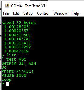 Do you have a circuit that would connect the NTC resistor and scale it to the ADC..?? We would have to go find something there...  |
||||
| lizby Guru Joined: 17/05/2016 Location: United StatesPosts: 3784 |
What variety of "doesn't work"? What is your code and what is your circuit? Please provide good pics of circuit. PicoMite, Armmite F4, SensorKits, MMBasic Hardware, Games, etc. on FOTS |
||||
| phil99 Guru Joined: 11/02/2018 Location: AustraliaPosts: 3290 |
Insert your thermistor specs. in the code below and choose a series resistor of similar value. Thermistor goes from pin 31 (GP26) to ground, resistor from pin 31 to 3.3V If you don't have the thermistor specs. accurately measure its resistance at two temps at the upper and lower ends of the range you want and plug them into the NTC Thermistor Beta Equation, which I can't find at the moment but it's on the Net somewhere. �beta = 4100 � � � � � � � � � 'thermistor specifications �R0 = 10000 : T0 = 25 �' Resistance (Ohms) at Reference Temp (Deg.C) �R1 = 10000 'R1 = series resistor, Ra = NTC Resistance (Ohms) at unknown Temp �SetPin 31, Ain �Do � �'SampleInput � �Vin = 0 � � �' Get 100 voltage samples, calculate mean, round off to 1mV. � �For Sample = 1 To 100 � � �Vinn = Pin(31) � � � �If (Vinn > 0.3) And (Vinn < 3) Then � � � � �Vin = Vin + Vinn � � � �Else � � � � � � � � � � � � � � 'detect input error � � � � �Vin = Vin + 1.72 � � � � �Print " Input out of range." � � � � �Pause 10000 � � � �EndIf � �Next � �Vin = Cint(Vin) * 0.01 � �Ra = R1 * Vin / (3.3 - Vin ) � ' Calculate resistance and temperature. � �Temp = 1/(1/(T0+273.15) + Log(Ra/R0)/beta)-273.15 � �Temp = Cint(Temp*100)*0.01 ' round off to 0.01 deg. � �Print Temp, Ra, Time$ � �Pause 2000 �Loop Edit. Here it is:- https://www.ametherm.com/thermistor/ntc-thermistor-beta NTC Thermistor Beta Equation: Beta = ln(Rt1/Rt2)/(1/T1 - 1/T2) Where: Rt1 = Resistance at Temperature 1 Rt2 = Resistance at Temperature 2 T1 = Temperature 1 (K) = Deg.C+273.15 T2= Temperature 2 in (K) = Deg.C+273.15 . Edited 2022-10-09 14:37 by phil99 |
||||
| Volhout Guru Joined: 05/03/2018 Location: NetherlandsPosts: 5931 |
MMBasic on PC does not support ADC. MMBasic on picomite and micromite support ADC MMBasic on Maximite support ADC PicomiteVGA PETSCII ROBOTS |
||||
| Mixtel90 Guru Joined: 05/10/2019 Location: United KingdomPosts: 8911 |
Just a point, which I'm not sure about. 10k NTC sensors are often available in various 2-wire forms. Is that what you meant, oh3gdo? If so, these are non-linear devices that can't simply be read into the ADC as they are pure resistance and it needs a voltage. Zonker has given an example of using ADC with a potentiometer input and phil99's example uses a fixed resistor from the supply rail to the ADC input, with the thermistor from the ADC to GND to form a potentiometer. The ADC input will give you the voltage at the pin so calculation will be needed to find the temperature, which phill99 has included in his example. Note that thermistors are inherently non-linear so can only be used over part of their curve unless steps are taken to linearise them. There are other more direct ways to read temperature at higher cost though. First, MMBasic supports the DS18B20 temperature sensor directly and returns the temperature in degrees centigrade. Another way is to use something like the MCP9701A, which is a thermistor with built-in linearisation. This produces a linear output voltage of 19.5mV/degree C. ...and welcome to the forum! :) Mick Zilog Inside! nascom.info for Nascom & Gemini Preliminary MMBasic docs & my PCB designs |
||||
| CaptainBoing Guru Joined: 07/09/2016 Location: United KingdomPosts: 2171 |
Hello of3gdo, welcome. you might find this useful |
||||
| oh3gdo Regular Member Joined: 18/11/2021 Location: FinlandPosts: 47 |
Hey, I got a lot of answers! The phil99 give a real program! When I used it with my PC, it doesn't worked, off cause. I required parameters, but I think it is normal. I have also a PIC/NTC c-language example http://remotesmart.wikidot.com/ntc-vastus At the end of file. Then I remember that I have tested Micromite about year ago. I have PIC32170F256B and it worked find. I found my prototype. The I thing how to use it as with normal LCD like 2*16. Can I found a working example? Regards Pekka |
||||
| Mixtel90 Guru Joined: 05/10/2019 Location: United KingdomPosts: 8911 |
There is an example of how to connect and use a LCD text display in the Micromite manual - which is what you need for the PIC32MX170F. Mick Zilog Inside! nascom.info for Nascom & Gemini Preliminary MMBasic docs & my PCB designs |
||||
| stanleyella Guru Joined: 25/06/2022 Location: United KingdomPosts: 2807 |
@oh3gdo . I am new and rpipico a to d is not good because of the power supply. It is noisy. This just takes samples and draws them but there is a better way that sorts the noise. It is in the manual somewhere Welcome to mmbasic. It is very good. A bit of learning new stuff but not difficult if you used basic before. It is big manual. SETPIN GP26, AIN cls for count%=0 to 237 samples!(count%)=(PIN(GP26)*50)+140 'get new samples old_samples!(count%)=samples!(count%) 'copy samples to old_samples line count%,samples!(count%),count%+1,samples!(count%)+1,1,wh 'draw first samples next count% ' do for count%=0 to 237 samples!(count%)=(PIN(GP26)*50)+140 'get new samples line count%,old_samples!(count%),count%+1,old_samples!(count%)+1,1,bk 'erase old_samples line count%,samples!(count%),count%+1,samples!(count%)+1,1,wh 'draw new samples old_samples!(count%)=samples!(count%) 'copy samples to old_samples next count% loop |
||||
| oh3gdo Regular Member Joined: 18/11/2021 Location: FinlandPosts: 47 |
Mixtel90 Thank you, I found the LCD code. It was very compact to compare my c-code. I have not read the full document. == Eejit I recommend that you filter the power supply. Just add a small resistor like 10--100 ohms and 100uF capacitor. It is much easier than filter the ADC result. == I just made a order Raspberry PI PICO 10 pcs. Let see what I am doing with them. == I am just doing an inclinometer for planter. It has two sensors, so that I can see what is a right tilt. It has separate sensors and LCD display. |
||||
| Mixtel90 Guru Joined: 05/10/2019 Location: United KingdomPosts: 8911 |
There are things you can do to improve the ADC. You can add a capacitor from VREF to GND. It won't help a lot because the series resistor is a low value. You can turn off the on-board switching supply by connecting 3VEN to GND then use a linear regulator to provide 3V3 to the system. This is highly recommended if you are using audio output. You can reduce the range of the ADC by connecting a LM4040 3V0 between VREF and GND then incorporating OPTION VCC 3.0 in your program. The reference voltage is then reduced from 3V3 to 3V0, reducing supply noise, but your inputs are now 0-3V rather than 0-3V3 so you have to watch that. If you are reading the ADC using value=PIN(GP26) or similar then the system takes a group of readings, discards the first and last then returns the average of what's left, so there is already some filtering present. This is all automatic. Mick Zilog Inside! nascom.info for Nascom & Gemini Preliminary MMBasic docs & my PCB designs |
||||
| Bowden_P Senior Member Joined: 20/03/2019 Location: United KingdomPosts: 174 |
Hi Mixtel90, Just above you say :- I couldn't spot any details about this feature of the A/D action in the manual. Do you know how many readings are taken or averaged ? With best regards, Paul. Nothing so constant as change. |
||||
TassyJim Guru Joined: 07/08/2011 Location: AustraliaPosts: 6538 |
10 readings, discard lowest and highest, average remainder. VK7JH MMedit |
||||
| JohnS Guru Joined: 18/11/2011 Location: United KingdomPosts: 4335 |
Bear in mind on the Pico that is of course still impacted by the hardware issues. John |
||||
| stanleyella Guru Joined: 25/06/2022 Location: United KingdomPosts: 2807 |
I was told to use that function ??? running picorpi from 3.3V lin reg and ground 3.3VEN does not get rid of noise. The stable adref I have not tried. |
||||
| lizby Guru Joined: 17/05/2016 Location: United StatesPosts: 3784 |
What kind of resolution are you looking for and for what purpose? What are you seeing in the way of noise? PicoMite, Armmite F4, SensorKits, MMBasic Hardware, Games, etc. on FOTS |
||||
| stanleyella Guru Joined: 25/06/2022 Location: United KingdomPosts: 2807 |
not https://www.youtube.com/watch?v=tmSHe1ZXyZQ using the pot wiper between 3.3V and gnd maybe more stable than floating ad |
||||
| Mixtel90 Guru Joined: 05/10/2019 Location: United KingdomPosts: 8911 |
You should never leave an ADC input floating. They have a high impedance input and you are guaranteed to pick up noise. Ideally, if you are feeding one from a pot wiper then you should also have a small capacitor (typically 100nF) between the wiper and GND to filter out noise as the wiper moves over the track. Mick Zilog Inside! nascom.info for Nascom & Gemini Preliminary MMBasic docs & my PCB designs |
||||
| stanleyella Guru Joined: 25/06/2022 Location: United KingdomPosts: 2807 |
It was reading temperature cls gui gauge #1, 120, 160, 100, wh, bk, 0, 3.3, 2, "T", wh do T!=PIN(TEMP) CtrlVal(#1) =T! loop |
||||
| Page 1 of 2 |
|||||
| The Back Shed's forum code is written, and hosted, in Australia. | © JAQ Software 2026 |
