
|
|
Forum Index : Microcontroller and PC projects : Puzzling problem for people who like puzzles!
| Author | Message | ||||
| PhilTilson Newbie Joined: 15/11/2015 Location: United KingdomPosts: 35 |
I am stuck with a problem which is defying all my attempts at solution. It's a little complicated, so really aimed at people who like to get inside a problem creatively! I have a heating control system that comprises a MicroMite Plus as the main processor and an ESP8266 as a link to the internet. The main processor does all the clever stuff, monitoring temperatures, determining when various valves and pumps should operate etc and the ESP keeps the RTC accurate by using internet time and sends log entries to a MySQL database on my ISP's server. It also acts as a web server, enabling control of the system from anywhere over the internet. This is summarised in the diagram. 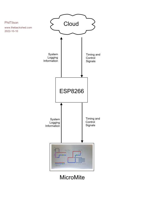 Both parts of the system are working perfectly! So, what's the problem? The system is based in Spain where the mains supply can be a little erratic at times. Although there is a backup battery, once in a blue moon, the main processor 'hangs'. I can tell when this occurs as the time on the web page freezes (the ESP keeps working fine). So I wanted to devise a means of resetting the MicroMite remotely. I added a button to the web page to allow for a System Reset and when this is 'received' by the ESP, it pulls an IO pin to ground for 500mS. Then I had to work out how to get that signal to the MicroMite over the ribbon cable. I decided to use pin 70 on the Micromite as this is brought out on the 40-pin connector and wasn't being used for anything else. This pin I linked directly to the 'hot' side of the reset button, so that when the ESP pulls its pin low, the MicroMite resets. And this works perfectly! BUT... When the connection is in place, if I cut the power to the system, then re-establish it, the MicroMite does not run. I investigated this and found that it throws a "Display not configured" error at the first line in the code which attempts to talk to the display (SSD1963 5" touchscreen). If I disconnect the pin70 line, it boots normally. But I have monitored the pin70 line and it stays high throughout. I even implemented a 1000mS delay between resetting and accessing the screen, but it makes no difference. So to summarise: Switch on system with pin70 line disconnected, boots as normal. Switch on system with pin70 line connected, throws "Display not configured". Switch on system, system boots as normal, then connect pin70 line system and it can be reset by remote command whenever required. I have appended the relevant start-up code from the MicroMite. All I have left out is a long string of declarations, none of which relates to pin 70 or anything likely to interfere. CONST dgy=RGB(127,127,127) 'dark grey CONST lye=RGB(255,255,192) 'light yellow CONST lgn=RGB(192,255,192) 'light green Pause(1000) RTC GETTIME open "COM1:115200" as #1 'Open COM1 to send diagnostgic data to attached port open "COM3:19200, 256, GetStatus, 24" as #2 'Open COM3 to send and receive data to WiFi if debug then print #1,"Calling Syslog at startup" syslog "500" + mid$(ver$,3) '[045][057] curDat$ = mid$(date$,9,2) + mid$(date$,4,2) + left$(date$,2) 'Clear the screen to light yellow cls lye <<<<< This is the line at which the error occurs ------------- backlight 100 If anyone can offer any helpful suggestions as to why this strange situation is occurring, I would be very grateful! More information available if required - but I thought this initial post was quite long enough already! Phil |
||||
| Mixtel90 Guru Joined: 05/10/2019 Location: United KingdomPosts: 8911 |
I don't know that chip. Pin 70 isn't a special one of some sort is it, and that's why it wasn't being used? Sometimes such things happen, I believe, and the pin is expected to be floating during boot.. Mick Zilog Inside! nascom.info for Nascom & Gemini Preliminary MMBasic docs & my PCB designs |
||||
| CaptainBoing Guru Joined: 07/09/2016 Location: United KingdomPosts: 2171 |
Hello Phil Hangs like this; I immediately suspect the internal voltage reference (1.8V) use a 47uF Tantalum for this and parallel it with a good quality 22nF ceramic disc to give as clean-a-reference as possible (don't know the pin numbers for you PIC - sorry) Big thing that struck me, no mention of a WATCHDOG timer(?). I think your plan of attack should be isolating the cause of the hangs, but next is recovery asap. Use a watchdog in your main loop, nothing too aggressive. If this doesn't reset the thing then I suspect deeper problems. External reset is a nice to have but should largely be un-necessary. The WATCHDOG is a software tweak that should give instant results. You can use a system variable to detect the reason for startup and log it if it was caused by the watchdog timer good luck! h |
||||
| Volhout Guru Joined: 05/03/2018 Location: NetherlandsPosts: 5931 |
I would add a series resistor 10k between esp and pin 70. This would prevent back powering and could help diagnosee if that pin 70 is associated to a different function. Even if temporary. PicomiteVGA PETSCII ROBOTS |
||||
| JohnS Guru Joined: 18/11/2011 Location: United KingdomPosts: 4335 |
Which CPU pin (by Microchip naming) is pin 70? Also, which PIC32 CPU exactly is it? John |
||||
| Mixtel90 Guru Joined: 05/10/2019 Location: United KingdomPosts: 8911 |
Micro is PIC32MX470F512L Pin 70 is RPD10/SCK1/PMCS2/RD10 if I read the data sheet correctly. A bi-directional I/O port. A local pull-up would be a good thing as you aren't supposed to have floating inputs - or depend on the chip's pull-ups if the input lead has any length. Edited 2022-10-10 03:08 by Mixtel90 Mick Zilog Inside! nascom.info for Nascom & Gemini Preliminary MMBasic docs & my PCB designs |
||||
TassyJim Guru Joined: 07/08/2011 Location: AustraliaPosts: 6538 |
If it is the explore 100 version, pin 70 is SPI so shouldn't be connected to reset. Connect to the reset alone and leave pin 70 free to do it's own thing... The explore 100 has an optional reset circuit included to cater for slow power supply rise time and brownouts. 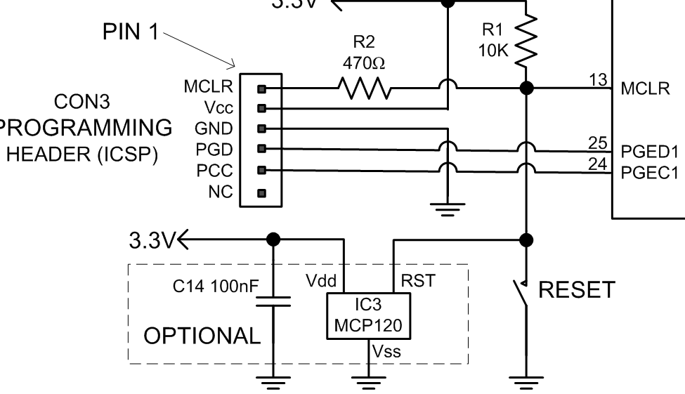 If your system doesn't' have that addition, now is the time to fit it. As a final protection, once the external issues have been fixed, use a watchdog in your program, but fix the problem first, or at least, record when the watchdog is activated. Jim VK7JH MMedit |
||||
| led-bloon Senior Member Joined: 21/12/2014 Location: AustraliaPosts: 209 |
You state "Although there is a backup battery" does this mean there are power outages that outlast this backup system? A circuit of this might show something lacking. Are they "brown-outs" or full "black-outs"? Have you done any data collection on outages? Using the ESP which appears to reboot ok, could monitor this and report? �Just some thoughts. led Just putting a reset control from the ESP may hide something a little more insidious than just a fail to reboot? Edited 2022-10-10 10:58 by led-bloon Miss you George |
||||
| PhilTilson Newbie Joined: 15/11/2015 Location: United KingdomPosts: 35 |
Many thanks for all the various responses. I will try to respond in turn to each one: Mixtel90/Volhout/JohnS/TassyJim: On this chip, pin 70 is just an IO pin. Yes, it is also used for other functions but, until specifically programmed for those functions, it's just an uncommitted pin. However, In an attempt to solve the problem, I physically disconnected the pin (by cutting the trace) from the 40-pin connector I was using to link the two processors, and it made no difference, so I have concluded that this was probably not the problem. CaptainBoing: Absolutely accept the need for good decoupling and have implemented same. I have also set the Watchdog timer, and at somewhat of a loss to explain why this does not reset the processor when it 'stops'. I can only conclude that the glitch, whatever it is (it only happens about once every couple of months) is sufficient to stop the processor completely so that it cannot reboot itself (not exactly sure how this aspect works!). TassyJim: Yes, I have the brownout/PSU MCP120 installed. However, see next point... led-bloon: The system is powered from a LiPo battery which is float-charged continuously from a plug-in PSU, via a LiPo charging regulator circuit. The battery lifetime when the system is idling is several hours, and although power outages of 12 hours are not unknown in this part of Spain(!) I don't think this is a likely cause of the problem. Since posting the original query, I resorted to a direct connection between the ESP and the reset button via a separate wire. The problem continued! Unfortunately, I don't have my test equipment over here, but I am wondering if there is some strange 'race' effect going on where the application of the power is starting up the ESP fractionally after the MicroMite which is therefore being reset, which is resetting the ESP etc. Sounds odd, but without a scope, I can't check for things like that. I will be taking a parallel system back to UK with me in a week or two and will carry out some more tests - and report my findings! Finally, I have circumvented the problem in a rather crude, but effective way! I now have a small pushbutton on the box. If I want to power-up from scratch, I hold the button in to disconnect the reset wire while I switch on, then release it, and all is well, and I can reset the MicroMite remotely. It wont solve the problem of the battery running out, though! Phil |
||||
| Nimue Guru Joined: 06/08/2020 Location: United KingdomPosts: 427 |
Seems like a marginal use case of: https://uk.switch-bot.com/products/bot-combo  Entropy is not what it used to be |
||||
| CaptainBoing Guru Joined: 07/09/2016 Location: United KingdomPosts: 2171 |
hmmm... it is fairly fundamental then. What are you doing with the PGD & PGC pins? I had a system than would would not start just like this and in the end it was something attached to one of those, putting it into some sort of programming state. Can't remember how I fixed it... possibly pull ups... I wish I could remember the precise cause and fix - it wasn't that long ago. going senile. |
||||
| PhilTilson Newbie Joined: 15/11/2015 Location: United KingdomPosts: 35 |
Nimue: Oh no, it's a lot more complicated than that! There's a set of solar tubes that need to be monitored for circulation, a gas-fired boiler to add heat when necessary, two 'ring mains' for hot water which need to be separately controlled at different times of day and an underfloor heating sysytem to be monitored! CaptainBoing: Nothing on PGD and PGC. Weird poblem but now solved, albeit rather clumsily! |
||||
| Mixtel90 Guru Joined: 05/10/2019 Location: United KingdomPosts: 8911 |
Ideally, if PGC and PGD aren't being used, the program should set them as outputs, either high or low it doesn't matter. This applies to all spare pins and reduces the possibility of noise and crosstalk getting into the system. Personally I don't bother, but I've never programmed anything that important and on the end of a long wire. If there's a PGM pin it should have 100k to GND. Edited 2022-10-11 01:14 by Mixtel90 Mick Zilog Inside! nascom.info for Nascom & Gemini Preliminary MMBasic docs & my PCB designs |
||||
| The Back Shed's forum code is written, and hosted, in Australia. | © JAQ Software 2026 |
