
|
|
Forum Index : Microcontroller and PC projects : Are these LCDs Usable?
| Author | Message | ||||
| Rickard5 Guru Joined: 31/03/2022 Location: United StatesPosts: 463 |
I just got handed 11 of These TFT Touch Sheilds from Seed Studios, does anyone have any ideas if I can hack them to a Picomite? I may be Vulgar, but , while I'm poor, I'm Industrious, Honest, and trustworthy! I Know my Place |
||||
| matherp Guru Joined: 11/12/2012 Location: United KingdomPosts: 11512 |
No: they are wired 8-bit parallel which is only supported for the SSD1963. Also, the touch screen does not have a controller so touch is not compatible either Edited 2022-10-14 02:50 by matherp |
||||
| Mixtel90 Guru Joined: 05/10/2019 Location: United KingdomPosts: 8911 |
The (PDF) circuit looks like they are SPI, but I've no experience of these. Mick Zilog Inside! nascom.info for Nascom & Gemini Preliminary MMBasic docs & my PCB designs |
||||
| matherp Guru Joined: 11/12/2012 Location: United KingdomPosts: 11512 |
Yes: I'm wrong about the display - sorry, shouldn't make assumptions based on the form factor. So it should work with the standard ILI9341 driver. The touch is though an issue as the board just exposes the raw resistive x,y dividers |
||||
TassyJim Guru Joined: 07/08/2011 Location: AustraliaPosts: 6538 |
If you really do want to use the touch facility, I came up with a circuit and code for reading the resistive sensors in MMBasic. The code was written for the Colour Maximite V1 and is 10 years old. It would need some updating to work with current versions of MMBasic. A better way would be to add the correct IC so the MMBasic touch commands could be used but my method only requires 2 or 3 resistors. https://www.thebackshed.com/forum/ViewTopic.php?TID=5291&PID=52791#52791#52791 and https://www.thebackshed.com/forum/ViewTopic.php?TID=5291&PID=52791#52791#52791 It was an interesting exercise that taught me a lot about touch screens. Jim VK7JH MMedit |
||||
| Rickard5 Guru Joined: 31/03/2022 Location: United StatesPosts: 463 |
Ya Know why the Picomite Thrills me so much ? before I retired I managed a few IT shops, and All the Worker Ants (except my IBM Man) Could Never do what you guys do here. it's like the old days when we still har Real USER GROUPS ,You guys Amaze Me post an Arcane question about Junkbox LCDs, and BOOM answers before Pie come! I love you guys I don't really have a Project for them Yet other than getting the screen part working, the touch part isn't as critical, Like I say they were hand-me -downs and I was deciding if it was worth keeping them I may be Vulgar, but , while I'm poor, I'm Industrious, Honest, and trustworthy! I Know my Place |
||||
| Mixtel90 Guru Joined: 05/10/2019 Location: United KingdomPosts: 8911 |
Rig one up on its SPI pins, use the ILI9341 driver and see what happens. It looks like you should be able to get the display and probably the SD card working. It'll be interesting to see what happens. :) By changing a link on the display you should be able to get control of the backlight too so that you can switch it off and on or PWM it. The necessary transistor is in place. Mick Zilog Inside! nascom.info for Nascom & Gemini Preliminary MMBasic docs & my PCB designs |
||||
| stanleyella Guru Joined: 25/06/2022 Location: United KingdomPosts: 2807 |
It looks compatible but not sure what logic levels it uses from the circuit. 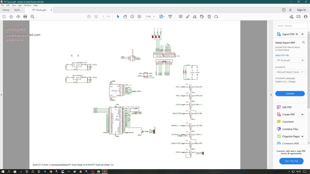 |
||||
| Mixtel90 Guru Joined: 05/10/2019 Location: United KingdomPosts: 8911 |
The display has a 5V input that feeds a 3V3 regulator (U3). The buffers U2 and U4 are being powered at 3V3 so they can accept 3V3. Each input has a 3K3 series resistor so I assume that inputs can also accept 5V. Outputs will be at 3V3, but that's within tolerance for 5V TTL. A further regulator produces 2V8 for the display logic and backlight. The base of the backlight transistor has 1K on it and is then linked to 5V to turn it on. Moving the on board link connects it to PD7 instead so it can be connected to a Pico output to control it. Mick Zilog Inside! nascom.info for Nascom & Gemini Preliminary MMBasic docs & my PCB designs |
||||
| Rickard5 Guru Joined: 31/03/2022 Location: United StatesPosts: 463 |
I found this Pin Out of the LCD Does anyone know how I'd wire these pins to the PicoMITE and what option config I'd use on the PM to config it? Thank you guys Digital pins Pin Name Function D0 NOT USED D1 NOT USED D2 NOT USED D3 NOT USED D4 TF_CS D5 TFT_CS D6 TFT_DC D7 BACKLIGHT(Selectable) D8 NOT USED D9 NOT USED D10 NOT USED D11 SPI_MOSI D12 SPI_MISO D13 SPI_SCK Analog Pins Pin Name Function A0 TOUCH PANEL A1 TOUCH PANEL A2 TOUCH PANEL A3 TOUCH PANEL A4 NOT USED A5 NOT USED I may be Vulgar, but , while I'm poor, I'm Industrious, Honest, and trustworthy! I Know my Place |
||||
| phil99 Guru Joined: 11/02/2018 Location: AustraliaPosts: 3290 |
Looking at the PDF it isn't clear where to connect Reset, but this might work for the rest. A bit of experimentation may be needed. OPTION SYSTEM SPI CLKpin, MOSIpin, MISOpin OPTION LCDPANEL ILI9341, LANDSCAPE, DC, RESET, CS Using the suggested pins. OPTION SYSTEM SPI GP18, GP19, GP16 Where D11 SPI_MOSI = GP19 D12 SPI_MISO = GP16 D13 SPI_SCK = GP18 OPTION LCDPANEL ILI9341, L, GP15, GP14, GP13 Where D6 TFT_DC = GP15 RESET ? TRST ? = GP14 D5 TFT_CS = GP13 . |
||||
| Mixtel90 Guru Joined: 05/10/2019 Location: United KingdomPosts: 8911 |
First - you can NOT use the PicoMite VGA firmware for this. The TFT_xxx pins are control pins for the display The SPI_xxx pins are for the SPI system The touch panel pins are for.... � (guess) - but we aren't bothered about those. So it depends on which PicoMite pins you want to use use. You need a set of SPI pins and some to use as control pins. From the manual.... You need SPI: OPTION SYSTEM SPI CLKpin, MOSIpin, MISOpin Try the ILI9341 driver: OPTION LCDPANEL ILI9341, OR, DC, RESET, CS OR is orientation - try L to be going on with Now look at what you have to work with: SPI_SCK is SPI CLKpin SPI_MOSI is SPI MOSIpin SPI_MISO is SPI MISOpin These can be either of the SPI devices on the PicoMite - your choice. TFT_DC is the DC pin (can be any pin as long as you specify it) TFT_CS is the CS pin (can be any pin as long as you specify it) RESET can be any pin as long as you specify it (It goes to TRST, which shorts out the reset input pin on the driver chip). The SD card only needs a CS signal as the data pins are connected to SPI. So... OPTION SDCARD xx From the schematic, the CS pin on the SD card socket is on TF_CS so xx is the pin that you connect to that. Edited 2022-10-22 17:00 by Mixtel90 Mick Zilog Inside! nascom.info for Nascom & Gemini Preliminary MMBasic docs & my PCB designs |
||||
| Rickard5 Guru Joined: 31/03/2022 Location: United StatesPosts: 463 |
Hey Thanks Guys I'm gonna wire it up first thing in the morning it's almost 3 am here and them Walker boys have been getting me in trouble all night the trouble with trouble is it always starts out as fun ;) AGAIN THANK YOU something Cool will come of this if I get it working :) Rick I may be Vulgar, but , while I'm poor, I'm Industrious, Honest, and trustworthy! I Know my Place |
||||
| Rickard5 Guru Joined: 31/03/2022 Location: United StatesPosts: 463 |
sorry Guys tried it 3 times and no Joy I may be Vulgar, but , while I'm poor, I'm Industrious, Honest, and trustworthy! I Know my Place |
||||
| Mixtel90 Guru Joined: 05/10/2019 Location: United KingdomPosts: 8911 |
What are you connecting where and with what options set? Also, if you are messing about with changing options, you must use OPTION LCDPANEL DISABLE before you can set up new options. Concentrate on just the display first. You'll need to set up the SYSTEM SPI and LCDPANEL options. The SPI pins must be on a valid hardware SPI port of the PicoMite. Once they are set you shouldn't need to mess with them again. Mick Zilog Inside! nascom.info for Nascom & Gemini Preliminary MMBasic docs & my PCB designs |
||||
| phil99 Guru Joined: 11/02/2018 Location: AustraliaPosts: 3290 |
Adding to the above, is the backlight enabled? Maybe it is working but invisible. |
||||
| TassyJim Guru Joined: 07/08/2011 Location: AustraliaPosts: 6538 |
Forget the Arduino pin numbers, they only confuse. Compare the schematic to the PCB layout and you will see which pins to use, including the RESET which you were missing. Jim VK7JH MMedit |
||||
| The Back Shed's forum code is written, and hosted, in Australia. | © JAQ Software 2026 |
