
|
|
Forum Index : Microcontroller and PC projects : Enacoder problem
| Author | Message | ||||
| oh3gdo Regular Member Joined: 18/11/2021 Location: FinlandPosts: 47 |
Hey, I have again a new problem. Now with Encoder. 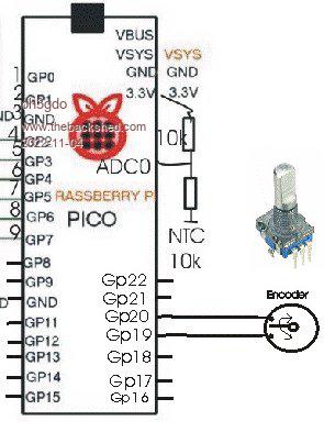 I did nor get pin 19 and pin 20 to go 3.3V I added 10k resistors from both to 3.3V. Now I got 3.3V, but it doesn't start the Inter sub program, when I connect Encoder signals to ground. Can somebody help me? Option Explicit Option default integer Dim Newcode As integer Dim Oldcode As integer Dim totalcode As integer Dim Number As integer ' Total code conversion Dim g(15)=(0,1,-1,0,-1,0,0,1,-1,0,0,-1,0,-1, 1, 0) 'gray code 0 1 2 3 4 5 6 7 8 9 0 1 2 3 4 5 'SetPin 19,din,pullup ' set pin 19 as input 'SetPin 20,din,pullup ' set pin 18 as input 'SetTick 1000,Inter 'Start inteterrupt for every 1ms in Inter-program SetPin 19, intl, inter, pullup 'goto Inter program, when PIN 19 goes from high to down SetPin 20, intl, inter, pullup 'goto Inter program, when PIN 20 goes from high to down progr: ' main program Pause 1000 ' small delay Print number,Pin(19), Pin(20) If Newcode=oldcode Then GoTo progr' if they have Not chaged got start totalcode=oldcode<<2 +newcode Print Bin$(oldcode,2),Bin$(Newcode,2),Bin$(totalcode,4) Print totalcode,g(totalcode) Number=Number+g(totalcode) Print "Number" Number GoTo progr Sub Inter' this is the interrupt program Newcode = Pin(19) + Pin(20)*2 Print "New" newcode oldcode = newcode <<2 End Sub Pekka |
||||
| lizby Guru Joined: 17/05/2016 Location: United StatesPosts: 3784 |
See here �for matherp's "patented switch-bounce immune rotary encoder I/F code". It's always worked for me. Is that a rotary encoder or a potentiometer? The rotary encoder modules I've used have had 5 pins. Edited 2022-11-04 03:08 by lizby PicoMite, Armmite F4, SensorKits, MMBasic Hardware, Games, etc. on FOTS |
||||
| oh3gdo Regular Member Joined: 18/11/2021 Location: FinlandPosts: 47 |
Hey Lizby. I have only two contact to ground. one to left the other to right. I have got it worked in CCS c-language, but now I do not get the pins to ground, although my multi meter shows ground. I try your link, but it said Error: PIN3 is invalid. Pekka |
||||
| Volhout Guru Joined: 05/03/2018 Location: NetherlandsPosts: 5931 |
Check you have corrwct firmware. The VGA firmware uses these pins tto generate VGA PicomiteVGA PETSCII ROBOTS |
||||
TassyJim Guru Joined: 07/08/2011 Location: AustraliaPosts: 6538 |
PIN 19 is not the same as pin GP19 You can use the physical pin numbers (pin 25 and 26) or GP19 and GP20 If you have external pullups, you don't need the PULLUP option but that shouldn't matter. Jim VK7JH MMedit |
||||
| lizby Guru Joined: 17/05/2016 Location: United StatesPosts: 3784 |
That code is not for the picomite--you would need to change the code to suit the pins you are using. PicoMite, Armmite F4, SensorKits, MMBasic Hardware, Games, etc. on FOTS |
||||
| Mixtel90 Guru Joined: 05/10/2019 Location: United KingdomPosts: 8911 |
@lizby 5-pin ecoders might be optical types with a led/sensor to read the track and may also contain a switch to Gnd. Most cheap ones use wiper switches to Gnd (although you can use them "upside down" with pull-down resistors and the wiper to VCC) and have no VCC connection. Some have one or two switch connections though. Mick Zilog Inside! nascom.info for Nascom & Gemini Preliminary MMBasic docs & my PCB designs |
||||
| lizby Guru Joined: 17/05/2016 Location: United StatesPosts: 3784 |
These are the rotary encoder modules I have used, which work perfectly with Peter's code. 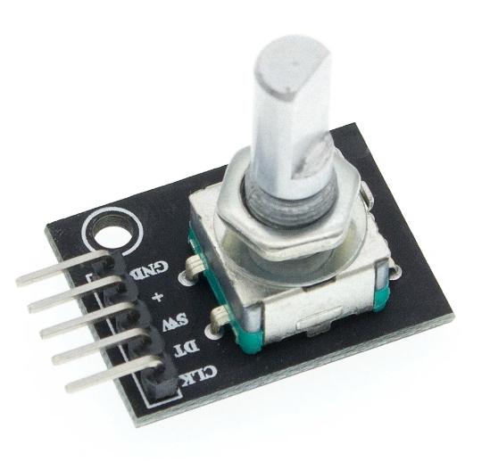 ~ Edited 2022-11-04 09:22 by lizby PicoMite, Armmite F4, SensorKits, MMBasic Hardware, Games, etc. on FOTS |
||||
| TassyJim Guru Joined: 07/08/2011 Location: AustraliaPosts: 6538 |
Using your existing circuit, this program should run (adapted form code written in 2014) ' simple encoder reading TassyJim Nov 2022 �SETPIN gp19, DIN, PULLUP' setup RB as an input �SETPIN gp20, INTH, RInt, PULLUP' setup an interrupt when RA goes high �DO � �' < main body of the program > �LOOP � SUB RInt ' Interrupt to decode the encoder output �IF PIN(gp19) = 1 THEN � �Value = Value + 1 ' clockwise rotation �ELSE � �Value = Value - 1 ' anti clockwise rotation �ENDIF �PRINT Value END SUB I tested without any external pullups and small capacitors (0.1uF) on both switch lines as debounce. Jim Edited 2022-11-04 11:45 by TassyJim VK7JH MMedit |
||||
| Mixtel90 Guru Joined: 05/10/2019 Location: United KingdomPosts: 8911 |
IIRC, lizby, those have pull-ups to + from clk, dat & Sw. All three are then pulled down when active. It's a simple wiper-type encoder, not optical. It's easy to check - an active encoder will have both VCC and GND to the encoder itself, as well as anything else. These are actually 4-wires: clk, dat, sw & common. Mick Zilog Inside! nascom.info for Nascom & Gemini Preliminary MMBasic docs & my PCB designs |
||||
| atmega8 Guru Joined: 19/11/2013 Location: GermanyPosts: 738 |
Works fine for me with an ALPS Encoder: 'Rotary Encoder SETPIN gp3, DIN, pullup SETPIN gp2, INTL, RInt ' Play around with INTL or INTH DO LOOP SUB RInt IF PIN(gp3) = 0 then counter = counter + 1 ELSE counter = counter - 1 ENDIF print counter; |
||||
| oh3gdo Regular Member Joined: 18/11/2021 Location: FinlandPosts: 47 |
atmega8 Thank you. When I loaded your program, it doesn't work. I checked my circuit and found that I have once mode put my wires one down. When corrected the numbers right PIN 18 and PIN 19, the circuit works find! Thank you. ' simple encoder reading TassyJim Nov 2022 SetPin GP19, DIN, PULLUP' setup GP19 as an input SetPin GP18, DIN, PULLUP ' setup GP18 as an input SetPin GP18, INTH, RInt, PULLUP' setup an interrupt when pin 18 goes high Do ' < main body of the program > If value <> 0 Then Print "Value", value EndIf Loop Sub RInt ' Interrupt to decode the encoder output If Pin(gp19) = 1 Then Value = Value + 1 ' clockwise rotation Else Value = Value - 1 ' anti clockwise rotation EndIf Print "value",Value End Sub |
||||
| atmega8 Guru Joined: 19/11/2013 Location: GermanyPosts: 738 |
Terve, i think this line is obsolete/redundant: SetPin GP18, DIN, PULLUP ' setup GP18 as an input Delete it, test it.. Edited 2022-11-04 23:19 by atmega8 |
||||
| oh3gdo Regular Member Joined: 18/11/2021 Location: FinlandPosts: 47 |
atmega, yes you are right. I tested it just now. Pekka |
||||
| The Back Shed's forum code is written, and hosted, in Australia. | © JAQ Software 2026 |
