
|
|
Forum Index : Microcontroller and PC projects : PicoMite IR Decoding / Sending
| Author | Message | ||||
| Nimue Guru Joined: 06/08/2020 Location: United KingdomPosts: 427 |
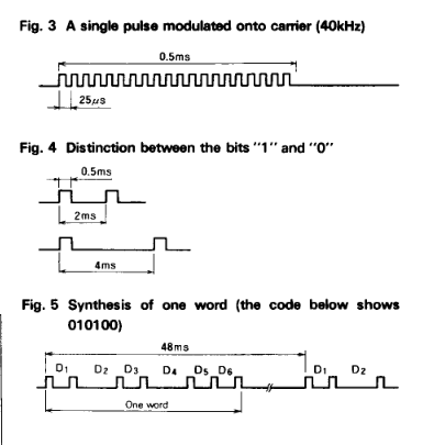
I have a thing for 1980's "robots" and toys. I have x2 of these:-  It is controlled via an IR remote. (It also has the capacity to have control sent via a serial port (at the back - which neither of mine have) - that will be phase II for me -- see if I can hack back in the serial control) x1 has a remote, the other doesn't. So I want to "clone" the working remote. Now the circuit inside the remove is simple - a diode and a M58480P chip -- so I could reverse engineer the circuit and build one (assuming I can get the IC) Chip details But, I can use the PicoMite and IR surely? I have a 40kHz IR receiver (plus a couple of 38kHz) on order to see if I can read out the codes sent by the working remote. If I cant get this via the PicoMite/IR I will fire up my oscilloscope to see if I can capture the signal / bit pattern directly. According to the data sheet, the IC uses a 40kHz carrier -- and 6 bit command words. I think I should be OK to read / decode the existing remote. But the PicoMite manual talks about 38kHz / 12bit for sending IR. Ok, so the built in "sending" doesn't look like it would work -- so time to roll my own. The datasheet talks about 2msec and 4msec intervals being a "0" and "1" -- so question: Can I modulate an IR diode fast enough to make "0" and "1", with each pulse being 25us << that's the big question I suppose. Any pointers on making a custom IR control? (Or can you buy remotes that just clone existing ones?) Cheers Nim Entropy is not what it used to be |
||||
| Volhout Guru Joined: 05/03/2018 Location: NetherlandsPosts: 5931 |
You can use a settick at 2 ms to create the timing framework and start-stop a 38khz pwm in the settick interrupts. PicomiteVGA PETSCII ROBOTS |
||||
TassyJim Guru Joined: 07/08/2011 Location: AustraliaPosts: 6538 |
Have a play with BITBANG BITSTREAM That's what it is ideal for. An array for each command either in DATA statements or built on the fly which will save memory and be more flexible. Jim VK7JH MMedit |
||||
| Nimue Guru Joined: 06/08/2020 Location: United KingdomPosts: 427 |
^^^ Thanks both. Something to build on -- hopefully I can decode the sending IR ;-) Will update when I make progress. Cheers N Entropy is not what it used to be |
||||
| Volhout Guru Joined: 05/03/2018 Location: NetherlandsPosts: 5931 |
Keep in mind that bitbang bitstream needs to specify each transition. A 2ms pulse of 38khz has 152 transitions. A IR command has 10-32 bits, meaning that worst case a command is a set of 4500 timing values. When variables are 64bit, that is 27kbyte, for each command. Very precise, and very universal, but very memory consuming. Maybe try to find if there is some info on the web about the exact protocol, or derive it from the chip datasheet and the frequency of the crystal or resonator of that chip. Edit: the chip is 6 bits. The bitstream idea will work . Define a bitstream 0.5ms of 38khz. And fire that in the 2ms settick . With only 30 keys, it is not hard to find the codes used by trial and error. Edited 2022-11-07 07:09 by Volhout PicomiteVGA PETSCII ROBOTS |
||||
| TassyJim Guru Joined: 07/08/2011 Location: AustraliaPosts: 6538 |
 Even encoding each full stream in arrays will be within the memory capabilities of the pico (unless there is a big main program) Jim VK7JH MMedit |
||||
| Volhout Guru Joined: 05/03/2018 Location: NetherlandsPosts: 5931 |
Some example code based on TassyJim's bitbang... 38kHz carrier frequency is 26us period time. The high time is 13us, the low time is 13us. The set of pulses is 0.5ms of 38kHz pulses, this is 19 pulses, resulting in 38 high times and 38 low times. This is exploited in below (blocking) code written around BITBANG BITSTREAM and PAUSE statements. 'bitbang_IR.bas test for bitbang bitstream option default none option explicit on const carrier% = int(1e6/38e3) �'38kHz in us const phase% = int(carrier%/2) �'half the carrier period time const bits% = 6 � � � � � � � � 'number of bits to send '0.5ms 38kHz carrier is 38e3*5e-4 = 19 cycles = 38 half cycles (phases) 'generate an array that contains the 38 time delays dim i%,data%,keycode% dim puls%(37):for i%=0 to 37:puls%(i%)=phase%:next i% 'Init GP0 as the transmit pin setpin gp0,dout 'here we define the data to be sent keycode% = 42 � � � � � � � � � � � � � � � �'just any code between 0 and 63 (6 bit codes) 'repeatedly send the code in "keycode%" least significant bit first do �for i%=0 to bits%-1 � � � � � � � � � � � � 'cycle through the 6 bits � � �bitbang bitstream gp0,38,puls%() � � � � �'leading pulse � �pause 1.2 � � � � � � � � � � � � � � � � '2ms - 0.5ms carrier - 0.3ms MMBasic delay � �if (keycode% and 2^i%) then pause 2 � � � 'when 1 bit then wait 2ms more until next pulse �next i% � �bitbang bitstream gp0,38,puls%() � � � � � �'terminating pulse �pause 50 � � � � � � � � � � � � � � � � � �'interword gap (pause until next keycode sent loop end an IR driving circuit can be as this one: 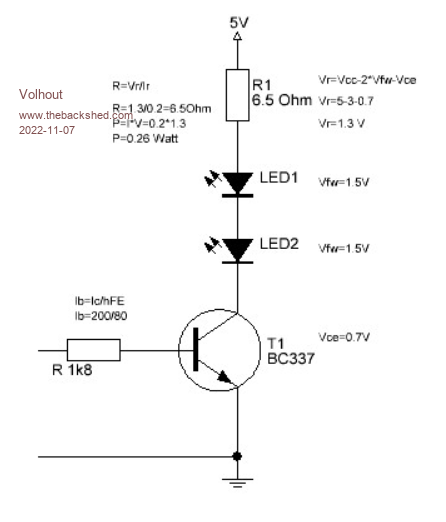 EDIT: documentation is a bit vague on "0" and "1" bit times. I thinki I got it correct in above code now. Edited 2022-11-07 20:23 by Volhout PicomiteVGA PETSCII ROBOTS |
||||
| Volhout Guru Joined: 05/03/2018 Location: NetherlandsPosts: 5931 |
Abstracted the IR transmite, preparation for IR receive. 'bitbang_IR.bas test for bitbang bitstream option default none option explicit const carrier% = int(1e6/38e3) '38kHz period time in us const phase% = int(carrier%/2) 'half the carrier period time const bits% = 6 'number of bits to send '0.5ms 38kHz carrier is 38e3*5e-4 = 19 cycles = 38 half cycles (phases) 'generate an array that contains the 38 time delays dim i%,keycode% dim a$ dim puls%(37):for i%=0 to 37:puls%(i%)=phase%:next i% 'setup --------------------------------------------------------------------------------------- 'Init GP0 as the transmit pin, and force low (IR LED off) setpin gp0,dout : pin(gp0)=0 'Init GP1 for interrupt low (IR receiver modules are default high, low when IR detected) setpin gp1,intl,IR_in 'main ---------------------------------------------------------------------------------------- 'repeatedly send the code in "keycode%" least significant bit first do 'send keyboard presses through IR a$=inkey$ if a$<>"" then 'when a key is pressed, send it keycode%=ASC(a$) and 63 'convert ASCII to 0...63 send_IR end if loop until a$=chr$(27) 'stop when ESC pressed end 'Interrupt ------------------------------------------------------------------------------------ sub IR_in 'do nothing yet end sub 'subroutines ---------------------------------------------------------------------------------- 'send keycode% using carrier bursts coded in puls%() sub send_IR local i% for i%=0 to bits%-1 'cycle through the 6 bits bitbang bitstream gp0,38,puls%() 'leading pulse pause 1.2 '2ms - 0.5ms carrier - 0.3ms MMBasic loop delay if (keycode% and 2^i%) then pause 2 'when 1 bit then wait 2ms more until next pulse next i% bitbang bitstream gp0,38,puls%() 'terminating pulse pause 50 'interword gap (pause until next keycode sent end sub PicomiteVGA PETSCII ROBOTS |
||||
| Nimue Guru Joined: 06/08/2020 Location: United KingdomPosts: 427 |
Upfront - thanks for the interest and input for this project. News: The standard IR decoding circuit doesn't detect / read the remote (not surprising). I did check that the circuit worked with another remote - an LG TV. 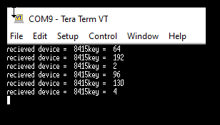 So the next thing was to dig up the 'scope: 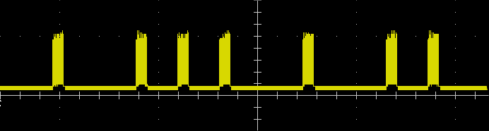 From this, the measured frequency of the carrier is 38kHz (as expected) The pulse shown is 100110 - which from the "1" button (if I remember correctly). It looks like each pulse is sent word is sent multiple times -- but from reading the manual, it appears that the device only responds to one pulse regardless of how long you hold the button. The device then "beeps" to say it is read for the next input. I need to investigate that more, but it looks like I can now capture the words/bits for the remote and then build upon the code here to make a custom remote. More updates to follow. Cheers N Entropy is not what it used to be |
||||
| Volhout Guru Joined: 05/03/2018 Location: NetherlandsPosts: 5931 |
Hi Nimue, Since the 70's there was quite a lot of development on the field of IR remote controls. It is no coincidence that Philips is already at RC6 or RC7 in IR remote control protocols. One of the things that was missing in the early remote control receivers was AGC (automatic gain control). Early receivers had a high gain and set threshold. Current receiver modules have AGC build in, to allow for a greater range �(not only further, but also closer). If you use a IR receiver with AGC, the gain is wide open when it receives the first burst of 38kHz light, and can cause a corrupted detection of the first pulse. Modern IR protocols adapt to this behaviour by sending a light burst ahead of the actual data, or they define the first IR burst to be longer. Additionally modern protocols have implemented checksums or CRC's (or send the message twice, but inverted) to improve reliability. The older systems, that cannot do this, can work around it by sending the message twice (only act when 2 identical messages have been received), or 3 times (majority decision). This is most likely implemented in the system you have, given that te IR protocol does not have a checksum defined.... Volhout Getting the X1 robot to work only requires the IR transmit correct ? Or is it a 2 way protocol ? You analyze the IR remote only to find out wat key is what command ? Edited 2022-11-09 19:26 by Volhout PicomiteVGA PETSCII ROBOTS |
||||
| Nimue Guru Joined: 06/08/2020 Location: United KingdomPosts: 427 |
Yes - not 2 way. The remote can work in two ways. One, as an actual remote -- press, direction keys, speed etc -- like an IR "radio controlled" robot -- very klunky. OR - you can press "program" mode and enter a sequence of keys (like BigTrack). When you've entered them all press GO and the robot does them in sequence -- up to 64 commnands. When programming a sequence UP RIGHT LEFT etc, the robot beeps after it receives each instruction, no matter how long you press the key on the remote for. Having scoped it, what seems to happen is that the key is sent continuously whilst the button is pressed. The robot ignores commands that are the same. So UP UP UP is ignored and what happens is that from the first UP it continues to go up until a different (STOP) command is given. Will wire up a basci IR transmitter and see if I can at least make it respond to the UP (forward) command --- from there, just a matter of getting all the keys. All that said, the thing is 40 years old and during this testing so far I've managed to break the wire / solder, so some fixing is needed firt. N Entropy is not what it used to be |
||||
| Frank N. Furter Guru Joined: 28/05/2012 Location: GermanyPosts: 1102 |
I did something similar to this many years ago. I recorded the signals with the oscilloscope and simply rebuilt them in the microcontroller - without paying further attention to the decoding. This worked very well! However, you would have to rebuild ALL 64 commands...  Frank |
||||
| Volhout Guru Joined: 05/03/2018 Location: NetherlandsPosts: 5931 |
I count only 25 buttons on the remote control... not 64... PicomiteVGA PETSCII ROBOTS |
||||
| Nimue Guru Joined: 06/08/2020 Location: United KingdomPosts: 427 |
Update: I've decoded the matrix (I think I just wanted to post those words!!!)... Once I set my scope up properly and soldered some temp wires to the remote control, this was quite easy - especially as there is no protocol to speak of -- press the button and the same code gets sent repeatedly until you release the button. 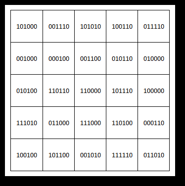 So, now to build a simple transmitter. Cheers N Entropy is not what it used to be |
||||
| Nimue Guru Joined: 06/08/2020 Location: United KingdomPosts: 427 |
It lives.... Turns out that the robot is quite sensitive to the timing of the pulses. It needs 40kHz (not 38kHz) and the data is in most significant bit format. @Volhout - modified your code sample: bitbang_IR.bas test for bitbang bitstream option default none option explicit const carrier% = int(1e6/40e3) '40kHz period time in us const phase% = int(carrier%/2) 'half the carrier period time const bits% = 6 'number of bits to send 'generate an array that contains the 40 time delays '40 transitions in data pulse dim i%,keycode% dim a$ dim puls%(39):for i%=0 to 39:puls%(i%)=phase%:next i% 'setup --------------------------------------------------------------------------------------- 'Init GP0 as the transmit pin, and force low (IR LED off) setpin gp0,dout : pin(gp0)=0 'Init GP1 for interrupt low (IR receiver modules are default high, low when IR detected) setpin gp1,intl,IR_in 'main ---------------------------------------------------------------------------------------- keycode% = 38 'hardcoded the value for "forward" send_IR 'Interrupt ------------------------------------------------------------------------------------ sub IR_in 'do nothing yet end sub 'subroutines ---------------------------------------------------------------------------------- 'send keycode% using carrier bursts coded in puls%() sub send_IR local i% for i%=bits%-1 to 0 step -1 'cycle through the 6 bits in reverse order bitbang bitstream gp0,40,puls%() 'leading pulse pause 1.2 '2ms - 0.5ms carrier - 0.3ms MMBasic loop delay if (keycode% and 2^i%) then pause 2 'when 1 bit then wait 2ms more until next next i% bitbang bitstream gp0,40,puls%() 'terminating pulse pause 50 'interword gap (pause until next keycode sent) end sub Delighted to report that the robot now responds to commands from the PicoMite + IR diodes. Final step to program up a remote of some sorts. Huge thanks to the pointers and help provided - great to see 1980's kit with a new life. N Entropy is not what it used to be |
||||
| Volhout Guru Joined: 05/03/2018 Location: NetherlandsPosts: 5931 |
Glad it works for you ! Keep us informed with your progress... PicomiteVGA PETSCII ROBOTS |
||||
| The Back Shed's forum code is written, and hosted, in Australia. | © JAQ Software 2026 |
