
|
|
Forum Index : Microcontroller and PC projects : PicoMite: driving a passive buzzer
| Author | Message | ||||
| matherp Guru Joined: 11/12/2012 Location: United KingdomPosts: 8572 |
"Real" loudspeakers act like primitive filters and will give a tolerable sound with unfiltered output. It is possible that the 44100Hz carrier is just locking up the buzzer without a filter so no output |
||||
| thwill Guru Joined: 16/09/2019 Location: United KingdomPosts: 3838 |
YES, that is what I am saying, though GP0 and GP1 in my case. I'll give it some more poking tonight and try attaching a headset rather than a buzzer, and I also have an 8R speaker somewhere. Best wishes, Tom Edited 2022-11-29 22:36 by thwill Game*Mite, CMM2 Welcome Tape, Creaky old text adventures |
||||
| Turbo46 Guru Joined: 24/12/2017 Location: AustraliaPosts: 1593 |
[QUOTE`=Tom]OK, so they are active buzzers and they work fine (with PWM) using Volhout's circuit from above with the PN2222 swapped out with the BC547s that I have. I even played a 2-channel version of "The Entertainer" on a pair of them using the PWM command, it was an experience not to be forgotten . But I get Sweet FA (with or without the low pass filter from the PicoMite manual) if I use the same setup with OPTION AUDIO, and PLAY TONE or PLAY SOUND. What detail am I failing to grasp ? Back to the original problem. It works with Volhouts simple inverter. That suggests to me that the speaker is effectively filtering out the frequencies that it cannot respond to as I said before. So why doesn't it work with OPTION AUDIO, and PLAY TONE or PLAY SOUND? I don't know but if they both use the 44100Hz carrier then it must be something simple. Software is your thing. Sort that out first. Mixing the channels is the next problem. It may be that Volhut's circuit could be used to sum the digital signals with two extra 2K2 input resistors but don't hold your breath. Bill Keep safe. Live long and prosper. |
||||
| thwill Guru Joined: 16/09/2019 Location: United KingdomPosts: 3838 |
Hi Bill. What frequencies it cannot respond to ? Unless I am fundamentally misunderstanding then if I am using PWM 1, 256 then (assuming an "ideal" that does not exist) I am sending a 256 Hz square-wave oscillation and the speaker plays some moderately nasty approximation of Middle-C. There is no carrier wave in this mode and the 'duty' seems to control the volume. By the way with the PWM command are dutyA and dutyB percentages, fractions, or something else, the manual doesn't appear to say. At the moment I'm not seeing a software problem, I'm seeing a "I am still working under some misapprehension" problem. If as @matherp says the 44100Hz carrier "locking up" these buzzers is "a thing" then that would explain it ... though my gut tells me there would have been at least an initial click, pop or hiss. That's by-the-by until the basic problem of getting PLAY TONE/SOUND to do something is resolved, or it is at least understood why they do not. And my understanding is that once that is resolved PLAY SOUND can handle up to 4 channels on a single PWMA/B pair ... some sort of audio Voodoo outside the scope of my current problems. I know I'm repeating myself but my understanding is that electronics engineering courses and historic electronics hobbying include a whole bunch of messing about with analog, audio, hifi, filters, etc. I've got none of that background which I suspect is the major contributor to this thread. Best wishes, Tom Edited 2022-11-29 23:36 by thwill Game*Mite, CMM2 Welcome Tape, Creaky old text adventures |
||||
| Volhout Guru Joined: 05/03/2018 Location: NetherlandsPosts: 3503 |
Tom, Just tried. Virgin pico, picomiteVGA 5.07.05rc8. OPTION AUDIO GP0,GP1 there is 44kHz on the GP1 and GP0 pins DO PLAY TONE 500,500 PAUSE 2000 LOOP There is a continuous 500Hz modulation on the GP1,GP0 pins. When I connect a 32 ohm headset between GP0 and GND I hear a clear 500Hz tone. No filter, no resistor, just headphone. This is not desired (overloading the pin driver inside the RP2040) but it works. If you add the transistor and 2.2k resistor (no filter) your speaker should produce an audible tone. Do NOT connect between GP0 and GP1, since the signals on GP1 and GP0 are the same, the difference is 0, so you hear ZERO..nada..nothing... PicomiteVGA PETSCII ROBOTS |
||||
| thwill Guru Joined: 16/09/2019 Location: United KingdomPosts: 3838 |
Thanks @Volhout. Time and family willing I will try this all again this evening. I'm 99.99% certain I wasn't doing that. Best wishes, Tom Game*Mite, CMM2 Welcome Tape, Creaky old text adventures |
||||
| Turbo46 Guru Joined: 24/12/2017 Location: AustraliaPosts: 1593 |
No, the manual doesn't tell you but I found this. This site might clear up a bit of what is happening with PWM to audio. I don't know what the device will respond to, nor do I know what your ears can respond to. I would be lucky to hear 5KHz so the improvement that Volhout's filter makes is of no consequence to me. I expect that what you hear when using the switching transistor is the audio harmonics in the signal filtered out by the frequency response of the device and your ears. Bill Keep safe. Live long and prosper. |
||||
| phil99 Guru Joined: 11/02/2018 Location: AustraliaPosts: 1776 |
"Volhout's filter makes is of no consequence to me. I expect that what you hear when using the switching transistor is the audio harmonics in the signal filtered out by the frequency response of the device and your ears." That is also my experience. This morning I have tested this Class-D push-pull amp. It gives more volume than a single transistor. The output filter makes no audible difference, though the scope shows it greatly reduces the 44kHz at the speaker. 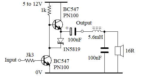 Transistor types, resistor and capacitor values are not critical. It just increases the amplitude of the 44kHz modulated square wave. These days most cheap audio stuff uses class-D. . |
||||
| Turbo46 Guru Joined: 24/12/2017 Location: AustraliaPosts: 1593 |
Thanks Phil that's a handy little circuit. For Tom's device which is apparently a piezo speaker with +ve and -ve terminals the AC output may not be a good thing. Maybe the electrolytic could be removed for that case? That's also why I think an H-bridge would not be a good thing because it would be feeding the device with effectively an AC signal. It IS good to reduce the 44kHz as much as possible if you are going to feed the audio into a hifi system with tweeters and a high frequency response. But for a simple circuit with an el cheapo speaker I wouldn't worry. Bill Keep safe. Live long and prosper. |
||||
| Mixtel90 Guru Joined: 05/10/2019 Location: United KingdomPosts: 5708 |
If it's a piezo or a passive magnetic type then an H bridge is ideal. If it's an active type then you can't use an H bridge. If Tom's device is actually a 16R magnetic type then it's a normal magnetic speaker so polarity is unimportant. Almost all of these things come with a + mark, whether they need it or not. It only actually applies to active devices, although it is used on speakers to show the polarity that causes the cone to move outwards. Used to make sure you get the phasing correct in multiple speaker systems. Mick Zilog Inside! nascom.info for Nascom & Gemini Preliminary MMBasic docs & my PCB designs |
||||
| Volhout Guru Joined: 05/03/2018 Location: NetherlandsPosts: 3503 |
One of the Russian review comments on this item was that it was a dynamic buzzer 16 ohm coil impedance (loudspeaker) component, not a piezo. Let's stick to that, so Tom is not needlesly confused. The single transistor and resistor buffer will be the simplest to implement. Regards, Volhout PicomiteVGA PETSCII ROBOTS |
||||
| thwill Guru Joined: 16/09/2019 Location: United KingdomPosts: 3838 |
Thanks for the extra input "overnight", So I had a play with PLAY TONE/SOUND using a speaker salvaged from a musical greetings card and the simple one resistor/transistor amp that was fine (if quiet) so I went back to the "buzzer" and of course to nobody's great surprise that now works too #$@&%*! It's very quiet (compared with the raw PWM approach) and rather clicky but it definitely works and I could swear it was dead as a doorknob despite all my efforts the evening before - Sorry! ... I wonder if it will still be working this evening ? I'm pretty convinced that is the case too. Presumably a piezo wouldn't be magnetic and this device is. Thanks Mick, I had wondered why there was a (+) on a speaker when (with my limited understanding) I didn't think it mattered. Thanks Bill, I've checked it out. My next step will be to build @Volhout's inductor free filter and see what effect that has - I'm just waiting on some capacitors. I'll also get a laptop speaker for the actual project: https://www.aliexpress.com/item/4001252606114.html How do I choose between a 4R or 8R speaker ... presumably the 8R speaker is quieter and takes less power ? As a thank-you for all your help I hope to put up a quick YouTube recording of my 3 voice/buzzer ragtime choir by the end of the week; I just need to cleanup the code to share. Best wishes, Tom Game*Mite, CMM2 Welcome Tape, Creaky old text adventures |
||||
| Mixtel90 Guru Joined: 05/10/2019 Location: United KingdomPosts: 5708 |
A 4R speaker will need more current to drive it. 4R is often used for car speakers as the amp is running from 12V so there is limited voltage available. Almost everything else uses 8R now, and that would usually be my preference. I don't know if you've seen them, but you can now get little Class D amplifier chips (PAM8403 - lots on ebay) that have an H bridge output and can take 4R speakers. That way you can get quite a loud amplifier (about 3W per channel, but the distortion at that level isn't good and you really need external filters on them) with only a 5V supply. It's not hi-fi but it's cheap. :) I've tried one of these with 8R speakers and they are actually not bad at all! Mick Zilog Inside! nascom.info for Nascom & Gemini Preliminary MMBasic docs & my PCB designs |
||||
| cosmic frog Senior Member Joined: 09/02/2012 Location: United KingdomPosts: 278 |
I use these for loads of stuff, cheap and sound great. link |
||||
| Volhout Guru Joined: 05/03/2018 Location: NetherlandsPosts: 3503 |
@cosmic frog, @mixtel90, Can you please check if PAM8403 works ? The PAM8403 changes a (small) analog signal into PWM (class D) and feeds it to the speaker. In picomite case there is no analog signal, there is a PWM signal (44kHz). If I feed that unfiltered to a PAM8403 you PWM modulate a PWM signal. That may very well not work at all. If you need to convert the picomite PWM signal to analog (the filter with inductor, or the 1 transistor active filter), then attenuate it, then feed it to the PAM8403, �you might as well connect the loudspeaker directly to the filter/buffer. Maybe Phill's solution is the best and simplest. Use the PWM at GP0/GP1 and use it to drive the speaker directly (via a 100uF capacitor), and it is tested !!! Regards, Volhout Edited 2022-12-01 00:22 by Volhout PicomiteVGA PETSCII ROBOTS |
||||
| Mixtel90 Guru Joined: 05/10/2019 Location: United KingdomPosts: 5708 |
I've not got a PAM8403 to test now 'cos I gave it to my daughter some time ago. You are correct though, it expects an analogue input and not PWM. Mick Zilog Inside! nascom.info for Nascom & Gemini Preliminary MMBasic docs & my PCB designs |
||||
TassyJim Guru Joined: 07/08/2011 Location: AustraliaPosts: 5895 |
I prefer the LM386 because it's output is ground referenced making stereo headphones easier to drive. I know - I am very old fashioned. Jim VK7JH MMedit MMBasic Help |
||||
| Mixtel90 Guru Joined: 05/10/2019 Location: United KingdomPosts: 5708 |
I agree, Jim. The PAM caught me out as I was expecting to be able to use it as a headphone amp originally. Mick Zilog Inside! nascom.info for Nascom & Gemini Preliminary MMBasic docs & my PCB designs |
||||
| Turbo46 Guru Joined: 24/12/2017 Location: AustraliaPosts: 1593 |
I'm glad the speaker type has been identified. Loudspeakers usually are marked + and - or have Red and Black terminals so you can get the phasing correct. If you connect two adjacent speakers out of phase with each other, they will tend to cancel each other. Bill Keep safe. Live long and prosper. |
||||
| matherp Guru Joined: 11/12/2012 Location: United KingdomPosts: 8572 |
TDA2822M is another useful headphone friendly chip. Obsolete now but still widely available in dip8 package which gives you a full stereo amp |
||||
