
|
|
Forum Index : Solar : Solar Hot water system (thanks to forum, Warpspeed and others)
| Author | Message | ||||
| KeepIS Guru Joined: 13/10/2014 Location: AustraliaPosts: 1864 |
Another stinking hot day in paradise, I moved the HWS controller and Solar Disconnect switch out of the weather and under the pergola, so much nicer for me to finalize some tests. First off, the FOD3182 High speed MOSFET (or IGBT) gate driver IC. Some may recall the RF oscillation I was encountering with the 555. This morning after the controller relocation, I noticed that the IGBT heatsink (SSR) was getting hot and the FOD3182 IC was stinking hot. Once again the only rational explication was some kind of RF on the switching line from the IC to the SSR gates (again). Grabbed the CRO and was greeted with a band of RF noise swinging 0 to 15v instead of a PWM square wave?? Turns out that IC1, the Opto coupled Gate driver, has lots of gain and can oscillate under certain conditions, hence that NOTE in the spec sheet requiring a 100nf connected directly across the supply pins of IC1, which I had ready have installed. The fault occurred ONLY under certain load conditions. I found that IC1 is very particular about the Cathode (pin 3) ground connection location, so I added a 100 ohm in series between Pin 3 and a 10nf to ground then a 47 ohm going to pin 3 of IC2, the NE555, which is, in this case, the comparator controlled output of the 555, this pin pulls the Cathode of the Optocoupler High [off] or Low [on]. I�ve thrown everything at it and it finally appears 100% stable - I really worked it. In the revised circuit, JP1 sits between the 555 IC2 and the OptoCoupler driver IC1, Pin 3 of both ICs. JP1 allows me to turn the OptoCoupler Driver on and turn the SSR hard on instead of having it Pulse, I use this for testing and comparing power output. � 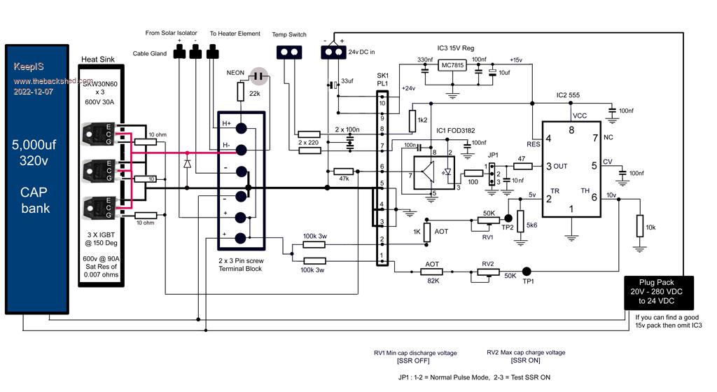 Following on from the tests carried out yesterday This morning I set the low cut off trip to 150v - Results: (A) The Pulse discharge time reduced to 98ms down from 135ms (B) The charge time reduced from 200ms to between 50 to 60ms (c) The Pulse rate around 7 times a second. The Pulse now discharges from 220v to 150v, and is now in a fairly linear part of the decay curve. Quick and dirty: Say the averaged voltage in the Pulse is around 187 volts. Then it looks like the Avg Pulse power is 1.46kw delivered for 100ms every 50ms or so into the load resistor. An initial test I did yesterday evening with a 24 ohm 100w resistor as the load, carried out in poor solar conditions, revealed something very interesting. With the load directly connected, it pulled the panel output down to 20v, so not much happened. Connect the controller and it still managed to pulse once a second, in around 4 seconds the resistors were too hot to touch, a few seconds more and the traditional spit test resulted in the boiling evaporation some of us know all too well. The Capacitor Bank may actually be working harder as they are operating at the peak discharge part of their cycle (MAX CURRENT) many time a second. To little capacitance and the current / power into the load would be limited, to much cap and the charge cycle would be extended greatly, and to a lesser degree, the discharge time, all resulting in a lower repeat rate. But keeping it simple, as size of the solar array increases (Power) then it would be advantageous to increase the size of the Cap bank accordingly. I notice with the higher repeat rate that the SSR Heatsink runs warmer - higher peak current so higher power. Looks like the seemingly slow repetition rate is not a hindrance when the pulse power is delivered to a Load that holds the thermal increase without cooling between pulses - a thermal bank - a well insulated HWS, especially once it starts to get warm, seems like it has snowball effect. � � Thought or Errors?? � Hope to do more tests later on today, I have to watch the heat at the moment just in case. Mike. Edited 2022-12-07 14:54 by KeepIS NANO Inverter: Full download - Only Hex Ver 8.1Ks |
||||
| Solar Mike Guru Joined: 08/02/2015 Location: New ZealandPosts: 1162 |
The FOD3182 only requires 10ma drive current for its led, with a forward voltage of max 1.8v. As your 555 is powered from 15v supply then you need to limit the drive current from pin 3 to 10ma ie 15v-1.8 = 13.2v, so use a resistor near 13k so you don't blow up the Fod3182 with excessive led drive. Cheers Mike |
||||
| KeepIS Guru Joined: 13/10/2014 Location: AustraliaPosts: 1864 |
Hi thanks for that suggestion, yes, I thought that at first, but I measured it and under 10ma. I think the spec was 10 to 16mA. I actually had a total 1.7k in series, the 100 ohm I added decoupled the earth and it's now happy. I could have fixed it with just moving the earth (tested and verified) but I just didn't feel like making the daughter board a 3rd time, so I just decoupled it. BTW: Just remeasured, the voltage is 1.4v @ 9.8mA Mike. Edited 2022-12-07 15:35 by KeepIS NANO Inverter: Full download - Only Hex Ver 8.1Ks |
||||
| KeepIS Guru Joined: 13/10/2014 Location: AustraliaPosts: 1864 |
This controller is really delivering to the HWS in this small solar panel system. I just now, 4.20pm, placed 1 liter of cold water in my 1.8kW jug. Put the system on direct and was greeted with 60v out and not much happening after a few minutes. Refilled with cold water and put it in Pulse mode, a few minutes later it's starting to boil, swapped to direct and that "pre-boiling" noise stopped, waited - nothing, switched back to Pulse and 4 seconds later starting to boil again. Just had another hot coffee. Tested with the 100w 24 ohm resistors again, direct solar, they did get a bit hot. Waited for them to get cold, hit them in pulse mode, almost instant frying of some of the resistors. Explains why the HWS gets hot so quickly, at around 5am it's slowly getting pulsed with a lot of energy, by 6.30 the rate is faster, by 8.30 it around 5 pulses per second and then 7+ pulses by 8.30am. This is an under sized solar supply and I have it set to Pulsed all the time now as it rarely gets to 150V (the low trip point) under the 2.4kW load. BTW: This morning the HWS ran from daylight to 7.30am, I remover the Controller and relocated it, finished around 11am and reconnected the HWS, 45 minutes later on the fast pulse settings it switched itself off - HOT!. Bet it won't do in winter, but then I'm going to double the solar power to it by then. Edited 2022-12-07 16:35 by KeepIS NANO Inverter: Full download - Only Hex Ver 8.1Ks |
||||
| KeepIS Guru Joined: 13/10/2014 Location: AustraliaPosts: 1864 |
FYI: Water from 150L HWS is still warmish despite us using it with abandon from midday yesterday. Got to love hot weather (but not for the panels though) Raining and storms until 6.00:am. Power outage for a few hours last night - felt guilty looking out and seeing the only visible light was from the storms setting our security lights off and lighting the yard up like a stadium - Turned them off. 6.30am Rain stops, gets little less gray outside, controller starts flashing slowly. 7.00am Flash rate increases. 8.00am Pulsing for a total discharge time of 700ms each second. 8.34am HWS switches itself off. Thermostat set as high as it can go. I think we're set for summer! - No more off peak water bills. Six X 10 year old 180W yellowed faded panels laying flat on a proverbial hot tin roof, siting on our pergola with almost no slope on the west side of the house. Unless something changes it looks like I've reached the end of this small part of my off grid adventure  Almost Christmas - can't believe it  An Early Merry Christmas to all on the forum. Mike. NANO Inverter: Full download - Only Hex Ver 8.1Ks |
||||
| Murphy's friend Guru Joined: 04/10/2019 Location: AustraliaPosts: 671 |
Thanks for all your information Mike, got me planning this for my next project. Would you know the current draw at the 15v line when its running flat out? I have some small, isolated, 15V DC/DC converter modules I could use if suitable. Also, what type diode is shown above, between IGBT's & terminal block? |
||||
| KeepIS Guru Joined: 13/10/2014 Location: AustraliaPosts: 1864 |
Good afternoon, The Diode is a Transient voltage suppressor (TVS) something like an 1.5KE350 or equivalent. Current on the bench supply during testing sat around 10mA to 15mA, when the Optocoupler triggered and the NE555 pulled to ground it indicated around 30mA. As I only had a 24V Supply, I decided to replaced the LM7815 Linear regulator with a small low costs DC to DC switching regulator board from Jaycar, 3V to 40V input and adjustable output up to 35V @ 3A, runs cooler and very stable, nice bright blue LED so easy to tell 15V DC is running. EDIT: Updated circuit with parts listed. � � �NOTE: The existing HWS temperature switch, if used, MUST be fully isolated from the HWS system Heating element, power cables and frame/earth. 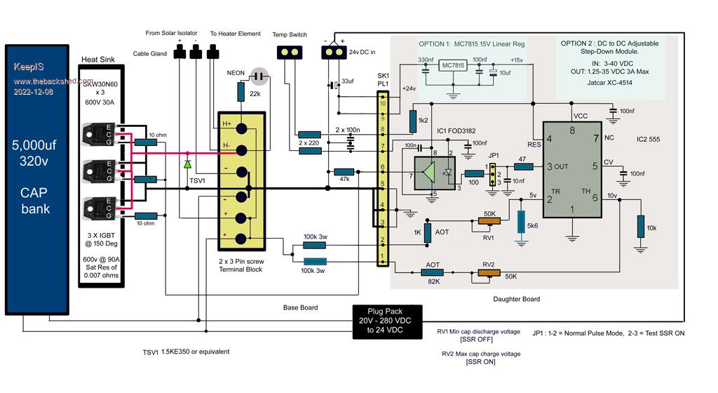 Mike. Edited 2022-12-08 17:35 by KeepIS NANO Inverter: Full download - Only Hex Ver 8.1Ks |
||||
| Murphy's friend Guru Joined: 04/10/2019 Location: AustraliaPosts: 671 |
Thanks Mike. I just rigged a rough breadboard version (no IGBT's on hand) and on an old analog milliampmeter the current was less than 10mA at the hi voltage side of my little power module, which I powered from 80V DC. These things do around 2W so it should be plenty. I will do a PCB as I have always found similar instability problems that you had with veroboard construction. |
||||
| KeepIS Guru Joined: 13/10/2014 Location: AustraliaPosts: 1864 |
The original circuit used MOSFETS, no changes to circuit, I just happened to have some IGBTs from and old grid tie inverter. I built the daughter board on standard Vero board (I'm very good with vero-board after 50 years of prototyping), the Base board is bare with no copper track. The IGBT are not soldered to the Base board directly, small links of thick wire connect the Pins to the baseboard, so replacing the IGBT causes no damage to the base board if they blow. Really should never have to touch the Base board if components are chosen correctly. I split it up as a Base board and a plug in Daughter board to Keep the Higher voltage DC (with respect to common) out of the daughter board, the higher DC is isolated from the Daughter board via 100k 3W resistors (I don't like surprises), making it plugin means it takes about 10 seconds to remove one screw and unplug it. Nice to modify and experiment with. The problems are not really the construction but an overlooked instability with the Driver, just needed to decouple Pin 3 from common, and add a couple of Bypass caps as shown and it's just rock solid now. Looking back on the older posts I see someone having trouble with high frequency instability apparent on the scope, it caused the SSR heatsink to run hot and other strange behavior, like being sensitive to the multi-meter probe location etc. These are no longer an issue. But it's nicer if you can get a board easily made, I am still a believer in Base board with plug in Daughter board, but to each his own. It's the end result that's important. BTW: I use two small 240 to 12v center tapped transformers, connected back to back, so I step 240 down to 12v the step up via the 6v or 12v tap to 180 or 256 volts DC. A bridge rectifier and very small cap (with 100k bleed) give me the DC output for testing [means the DC is insulated from earth]. It will slowly charge the Big cap bank and make it easy to set the switching points on the charge/discharge cycle before connecting the solar panels. Mike. NANO Inverter: Full download - Only Hex Ver 8.1Ks |
||||
| KeepIS Guru Joined: 13/10/2014 Location: AustraliaPosts: 1864 |
Well I though I was done, but, the hysteresis of the standard inbuilt HWS thermostat is to high. HWS fully heated again at 8.45am, using hot water throughout the day, must be at least 20 liters and it's still won't switch back on, water is still stinking hot at the outlet and taps. This is fine on Mains power, but on solar, I want the thermostat to cycle over a much narrower range. Since I'm not familiar with HWS internal design with respect to temperature variation throughout the tank, the question is: Does anyone know the best place to "EASILY" fit a small K-type thermocouple sensor. By that, I mean a known location where the HWS will not overheat (past design limits, thermal trip being activated) as a result of using the readings from the small thermocouple measuring point to regulate overall temperature. It's a small 50L 2.4kW DUX. Mike. NANO Inverter: Full download - Only Hex Ver 8.1Ks |
||||
| phil99 Guru Joined: 11/02/2018 Location: AustraliaPosts: 2579 |
"a known location where the HWS will not overheat (past design limits, thermal trip being activated)" Next to the current one. The manufacturer must think that is a good place. With your setup set the max. to 1 or 2 degrees below the current one and you won't need any differential. |
||||
| KeepIS Guru Joined: 13/10/2014 Location: AustraliaPosts: 1864 |
Thanks for the reply, the unit being only 6 month old, I really wanted to avoid pulling the thermostat assembly just to see if I could get access to the mounting surface, or exactly how deep the existing Sensor may be embedded into the cylinder? I'll do that as a last option, but was hoping someone had done something like this before successfully without removing/modifying the existing mechanical thermostat. NANO Inverter: Full download - Only Hex Ver 8.1Ks |
||||
| phil99 Guru Joined: 11/02/2018 Location: AustraliaPosts: 2579 |
The working and safety thermostats are usually just clamped to the side of the cylinder, a little above the element. It's many decades since I last saw a pocketed thermostat. Also have a heat pump HWS with too much differential (15 C) so I used some thin (0.6 mm) copper sheet to clamp a thermistor to the tank. One end is wrapped around the thermistor and the other flat end is sandwiched between the tank and the existing thermostat. Heatsink goo applied to all surfaces. Works well with a cheap controller. . |
||||
| KeepIS Guru Joined: 13/10/2014 Location: AustraliaPosts: 1864 |
Thanks, sounds like a really good idea, I have a feeling this thermostat is almost acting as thought it's sticking slightly, since adjusting the thermostat through it's full range a few times it appears to be switching on a bit earlier? When I get a chance, I've decided to have a good look and it and as I have thin copper sheet, HS paste and a thermistor on hand, I'll do what you did while I'm at it. NANO Inverter: Full download - Only Hex Ver 8.1Ks |
||||
| KeepIS Guru Joined: 13/10/2014 Location: AustraliaPosts: 1864 |
Some interesting finds on the net and a few Scope Waveforms: There was a post on the previous main topic started by Warpspeed. It was about a YouTube video of what appeared to a similar controller, but no real circuits or other help was forthcoming. A few people attempted to built the unit but had little or no success or help from the video uploader. I found the video and realized that it's implemented in a different way, more net time revealed it was a supplemental add-on next to the main MPPT controller and used excess panel output when the main system was not under load. Some A/B comparisons were shown on a digital meter readout and, well, not going there! Then I found another similar device for sale and lots of usage data and savings made over a year or so on, it's in following links. Makers site User Review Some Screen shots: I have adjusted the controller to work around the MPPT of the panels: The Panel voltage is not dropping much at all, it's a high DC voltage with a small a saw-tooth waveform at the top. The Panels only have to charge the cap up by 50V out of the CAPS 215v charge, so the inrush current is low and does not pull the solar voltage down by much - keeping it around the MPPT level. � The Panels: The VOC should be 267v but it's only 235v on these old panels. Max Power is @ 222v, but I've had to reduce it to 215v, again, old panels. � As the Screen shots will show, I'm charging/discharging the cap around 50V between 165v and 215v. NOTE: The Scope is connected directly across the Heater Element. The Controller Pulse width is set so that the Pulse decay is in the linear part of the R/C discharge cycle. The saw tooth part is the CAP bank charge / discharge cycle �into the Heating element from the High cutoff point of 215v, down to the low voltage cut off point of 165v, then the cap recharges and the cycle repeats. As conditions change, the charge Pulse width changes constantly as it tracks the solar change. The charge Pulse-width is the bright flat part at the bottom of the waveform. �� � � 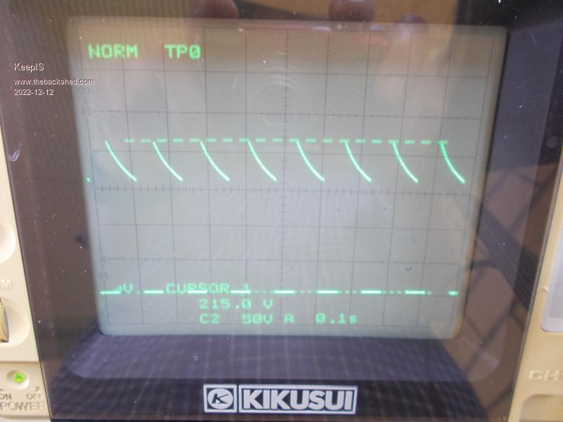 This shows the 115v voltage across the Element with a direct connection for comparison. 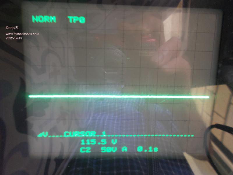 The direct 115 volts (dash line) in comparison to the Pulse voltage swing. 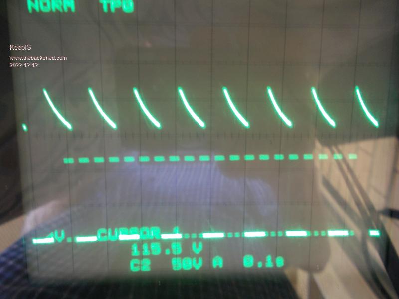 A closer look at the charge/discharge cycle. 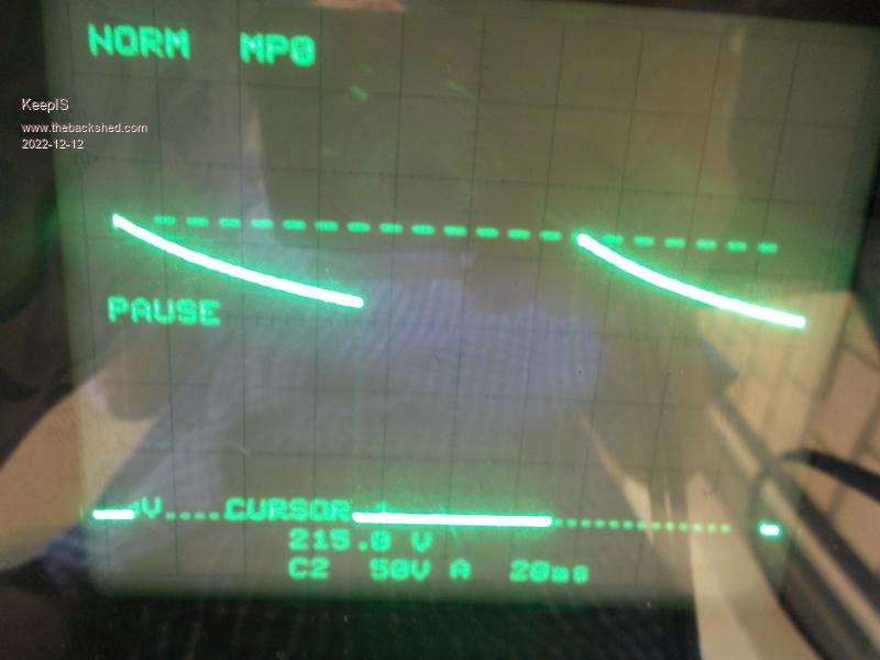 So a few days ago I decided to run the HWS to almost cold, pretty easy to do with 50L. The first morning I did, it turned out to be one of the most miserably low solar output days. The output from the solar panels [direct to the element] was 18v at a few mA at 9.00am, so nothing. Switched back to the solar controller, the neon was flashing at around once a second, sometimes less, so one burst of 1.5kw for 1/10 of a second, not much but better then direct. By 10am it was at 3 a second and HWS was warming, by 12.30 it was flashing at 7 x 1.5kw pulses a second as the first glimpses of sun popped up. It switched off at 2.15pm. The calculated heating time for a continuous 1.5kW feed is around 4 hours, so counting from 9am to 2.15pm it took 5 1/4 hours, would not have done that direct. The second day started out the same, but came good at around 9am and the HWS switched off at 12.30. All of the heating was in pulse mode, even when I'm getting 8 pulses per second, the direct voltage drops to 115v or less, 480w to 540w to the element, but 8 pulses roughly equate to 1/2 a second @ 1.5kW verses 1 second @ <540w. When I change the system over from an old 1kW of panels to a 2kW system, obviously the results will be so much better. This small system was only meant to be an emergency backup during extended blackouts, to at least have a hot shower now and then, but it's more than that, and I realized that if one of us has a shower at 3pm instead of 7pm, the HWS will have around 2 hours of heating time left, there are many ways to lower HWS usage at night in long blackout situations, and still have comfortable existence. BTW we still haven't turned the off Peak system back on. � Finally, the Controller flashing away in its new sheltered location, can't miss the flash with the camera as no visible off time between flashes with decent solar, just a flashing brightness change. � 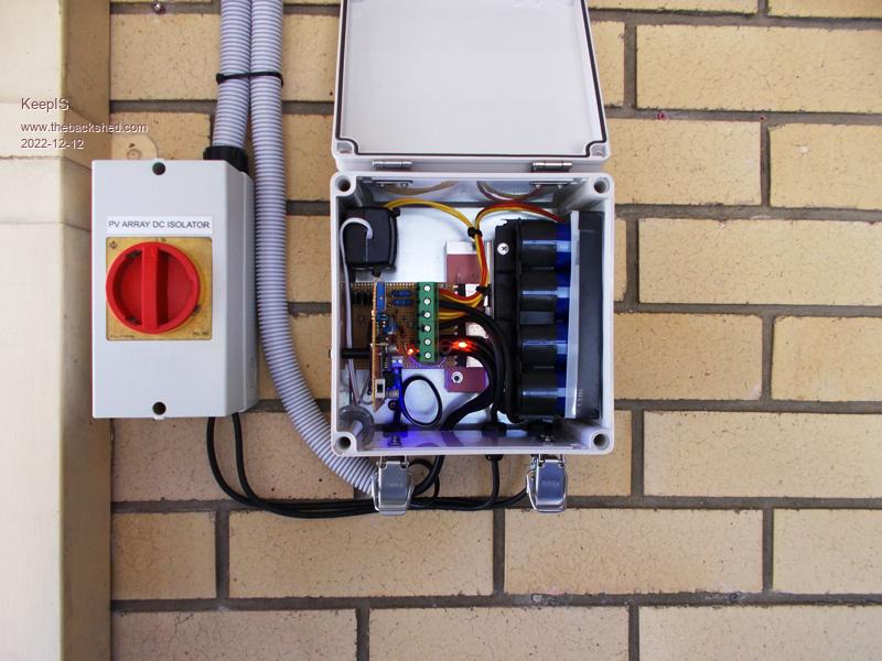 This is easy to adjust, I have wired the 2 x 50K 10 turn variable resistors in a way that means turning clockwise will raise the High or Low cutoff voltage, obviously counter CW lowers them. The Top Cut off can be set to the Highest voltage that will allow the Controller to still charge the cap in poor solar conditions. The low cutoff is the harder to set as it's dependent on the element resistance, total Storage capacitance, and panel current/voltage. I've think I've come up with a simple quick way but I just need the time to get a low cost item and test it. Mike. Edited 2022-12-12 16:12 by KeepIS NANO Inverter: Full download - Only Hex Ver 8.1Ks |
||||
| KeepIS Guru Joined: 13/10/2014 Location: AustraliaPosts: 1864 |
I thought I would finalize the Digital Scope information: I've added a basic description of the waveform for anyone not familiar with a CRO (cathode ray tube oscilloscope) which this digital storage scope that I'm using IS. � I have the Panel and Cap-Bank voltage waveform on CH2 [sawtooth waveform] with the Gate Drive PWM signal [square wave] on channel 1. Note: The gate drive volts is shown as 21.95v, however it's been referenced to the base line, not the the elevate cursors of CH2, it's actually just under 15v and is measured directly at the base of one of the IGBT devices after the 10 ohm gate resistors. The leading part of the sawtooth waveform is the charge time, the trailing part is the decay [discharge] time. The waveform is synchronized with the Gate drive. � 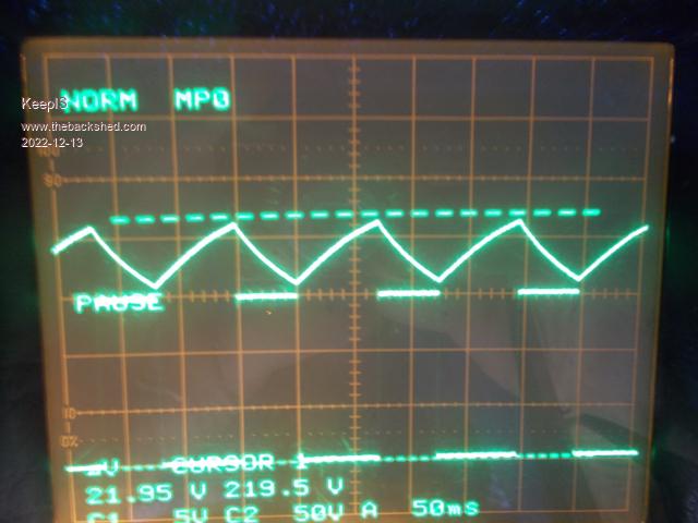 Zoomed image - Charge cycle is in the middle. 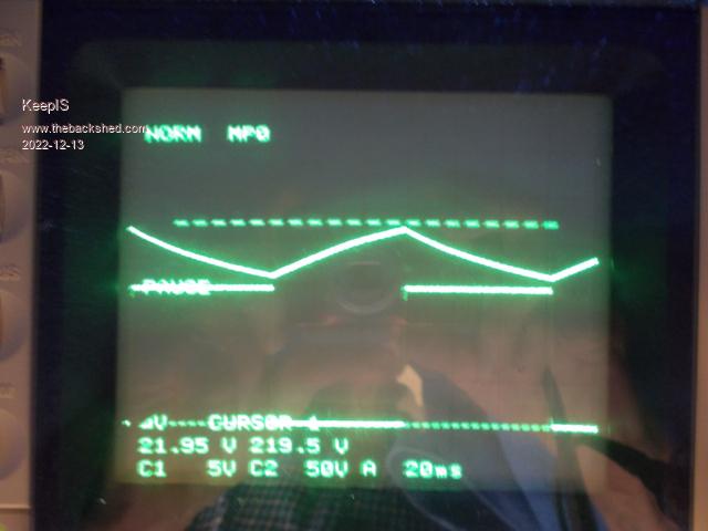 The following is the CAP Discharge across the heating element [CH2], and Gate PWM drive [CH1] 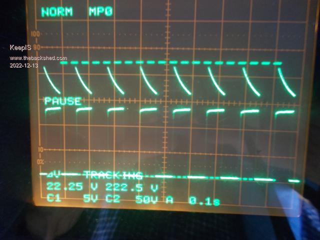 Zoomed image. 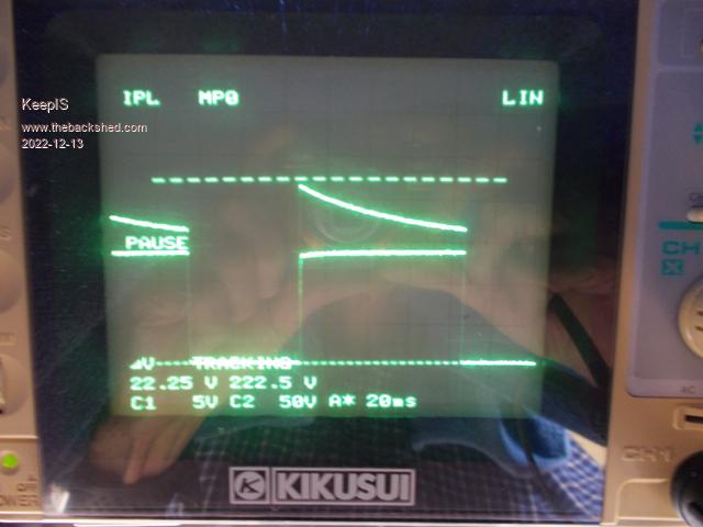 FYI, the slight roll off on the leading edge of the PWM Gate drive signal is a result having the PWM probe running without a ground clip. Reason? The Probe for the Element is connected ACROSS the Element connections, so the earth on that probe is effectively connected to the Cap Bank positive [220v], the probe earth clip is connected to the collector of the IGBTs. A slight interaction with the PWM probe but not enough to make me bother to adjust the Probe compensation. Mike. Edited 2022-12-13 11:37 by KeepIS NANO Inverter: Full download - Only Hex Ver 8.1Ks |
||||
| KeepIS Guru Joined: 13/10/2014 Location: AustraliaPosts: 1864 |
I notice that the Discharge time of the CAPS into the element is varying between 35ms and 55ms. This is controlled by the R/C TC of the Restive Element and CAP bank Capacitance and the HI/LOW voltage trip points of the NE555, so I decided to have a look. To start with, I eliminated the chance of excessive loss between the Controller and the HWS Heater Element. Measured straight across the Heater terminals in the HWS with the Scope and everything was exactly the same, and the element resistance never changes. The 555 and driver supply is absolutely rock solid, verified with the CRO. There are ZERO current paths on the control circuit board [daughter board], all current paths are located on the Base Board, and all IGBT positive and Collector switching paths are at the base of those two BIG green connecting blocks. So I believe that the NE555 trip point is being triggered earlier or later depending on how fast the charge rate [voltage] is traveling as it crosses the trip points, and a higher Panel output power would mean a faster turnaround time after crossing the Low trip point [recharge time], I had noticed the voltage points moving a bit between different tests that I've done over time. Anyway, it's working great so I'm going to leave it be. FYI: New Test to time the heating of a measured volume of water to 60deg from the same base temperature. Device in use: 2kW Jug. Overcast dull light. Time 4pm. Tested with the Controller first, it took 5.53 minutes to get to 60 deg (only 2 pules a second). Refill for the Direct from Solar test. I cooled the element down first but any heat left also favors this Direct solar test. After almost 6 minutes the Jug temperature had stalled at 36 deg for almost a minute. Light level was dropping and I switched to the Controller, the water temperature immediately started to climb, 4.20 minutes to 60 deg despite slowly fading light level. This jug has a blue LED light in the base, in direct mode it's very dim, in Pulse it's a very bright flash for each pulse. Even 2 Pulse a second are enough to slowly heat water to boiling, and it never stalls, it just keeps increasing the temperature, that's the difference between a few hundred watts direct (or a few watts in low light) and a slow (in poor solar conditions) repetitive 1.5kW energy pulse into a thermal bank, at the same time the controller is still keeping the Panel output around the MPP area. To recap, it's now been a week off grid with this little Solar Hot Water system - I'm going to double the size of the Panels in a few weeks and then see what I can get out of the Big HWS, might just be able to heat it in summer and use the little one for winter if needed, time will tell. Cheers Mike. NANO Inverter: Full download - Only Hex Ver 8.1Ks |
||||
| KeepIS Guru Joined: 13/10/2014 Location: AustraliaPosts: 1864 |
Small update: 48 to 240v Inverter. I've been busy scavenging for some big Toriods and reading over the numerous fantastic threads on this forum. For days now, and so much brilliant tech info. Feel like I've built a dozen inverters before I even start. Just started unwinding the three toriods I found -   . .The Solar HWS Controller: I really need to build a load that reaches equilibrium with a given power and holds it for a period of time, then responds after 20 seconds or so to an increase or decrease in PULSED DC into the load, that will now have to wait, and more old panels are here for HWS, just got to fit them. For the past week I've have the pulse rate around 14 to 20 pulses a second, in good light, from the available solar output. Pulse DC is now swinging between 190v and 220v, so right up at the MPP area for these panels. From what I'm seeing over a wide range of low cutoff settings, the Controller pulsing appears to be generating more power even when the solar output is high enough to sustain an average of around 400 watts direct DC to the HWS, this out of a max of 800 watts that I've seen briefly under ideal solar conditions. The main HW System is still switched off Still using the solar panel driven small HWS as normal. It's consistently switching off at the hottest thermostat setting by 10.45 AM. We use hot water throughout the day and it switches back on around 3.30pm to 4pm and the NEON stops pulsing around 5.30pm to 6pm. As others have suggested, keeping it pulsing appears to negate any burning of the thermostat contacts when they open, but I need to verify this 100% over a sustained period to be 100% sure, but logically it should be OK, especially as at higher pulse rates. Merry Christmas to all. NANO Inverter: Full download - Only Hex Ver 8.1Ks |
||||
Revlac Guru Joined: 31/12/2016 Location: AustraliaPosts: 1151 |
Thanks for the follow up, much better having the high power pulses vs direct, when you switch back to your large HWS, there is obviously more water to heat up initially, I think it will just take longer to heat, it should still have some heat in it for the next day and should heat up to full temp before the end of the day. When I had this HWS running direct solar, it took all day but was plenty hot enough for several showers despite the amount of water that had to be heated. I reckon the high power pulses from the controller should have my HWS done by midday, I'm still losing some heat from the tubes in the stove boiler, but I can work with that, A full cloudy day I just get the fire going, try to avoid that warm water Bacteria growth. Might be some other uses for this controller, running restive loads. I wrote the above a while back and misplaced it.  Your setup is working very well, as the heating is done by 10:45am and the pulses are good and fast, I don't see any need for over paneling the system at least for sunny days anyway, best to have it pulsing instead of full on, things might change a little in winter, we will have to wait and see, but the results so far are good. Thanks for the details on it working.  Looking forward to your inverter build.  Cheers Aaron Off The Grid |
||||
| KeepIS Guru Joined: 13/10/2014 Location: AustraliaPosts: 1864 |
Thanks, the extra panels will be to allow the large HWS to be heated, I will still be running it pulsed mode at all times as this is really impressive with this type of heating load / thermal bank. In winter and days of bad weather, the extra panels will obviously allow me still heat the small HWS for hot showers. All the good 400W panels are dedicated to running the house off grid, the donated / salvaged panels will handle the HWS. Yes, I'm aware of the problem with warm water and health issues, another advantage of a small system as the water is replaced almost every day. I'm not looking forward to winding the inverter toriod, still deciding on a 2 or 3 stack toriod, I figure over build it once and I should never have to touch that part of the inverter again. Cheers Mike. NANO Inverter: Full download - Only Hex Ver 8.1Ks |
||||
| The Back Shed's forum code is written, and hosted, in Australia. | © JAQ Software 2025 |
