
|
|
Forum Index : Microcontroller and PC projects : PIO explained PICOMITE
| Author | Message | ||||
| matherp Guru Joined: 11/12/2012 Location: United KingdomPosts: 8569 |
Clearing isn't an issue - just wasn't being done pio_sm_clear_fifos(pio,sm); |
||||
| Volhout Guru Joined: 05/03/2018 Location: NetherlandsPosts: 3496 |
That must have been there for even. It is due to the training course that it surfaced.. Thanks Peter for fixing it !!! PicomiteVGA PETSCII ROBOTS |
||||
| Pluto Guru Joined: 09/06/2017 Location: FinlandPosts: 328 |
Improved version of the PIO Instruction Reading program. Updates the output table on the console as more instruction lines are identified. Inserts (hopefully) understandable explanations after each instruction line. After a few updates on the console table, the PIO program continues to run w/o any new table updates. Just (ctrl-C) stop and re-run if there are unidentified/missing program lines. Output after a few iterations: ***************** EXCECUTE CONTROL ******************************** JMP_PIN 0 (The GPIO used as condition for JMP PIN.) WRAP_TOP 31 (At this address, execution is wrapped to wrap_bottom.) WRAP_BOTTOM 0 (After reaching wrap_top, execution is wrapped to this address.) ***************** PIN CONTROL ******************************** SIDESET_COUNT 0 (nbr of SIDESET pins) SET_COUNT 2 (nbr of SET pins) OUT_COUNT 1 (used with OUT PINS, OUT PINDIRS, MOV PINS) IN_BASE 0 (lowest IN pin) SIDESET_BASE 0 (lowest SIDESET pin) SET_BASE 0 (used with SET PINS, SET PINDIRS) OUT_BASE 2 (used with OUT PINS, OUT PINDIRS, MOV PINS) ****************** PIO instructions *************************** Details in RP2040 datasheet p.321-328 ***************************************************************** ifE source ifF operation delay/ cond bit cnt side- sourc address hex cmd set dest index DDDDD 0 &hE083 111 00000 100 00011 SET PINDIRS. to 00011 SET_BASE GP0 1 &hE000 111 00000 000 00000 SET PINS. to 00000 SET_BASE GP0 2 &hA0EB 101 00000 111 01011 MOV From NULL To OSR; Invert (bitwise complement) 3 &h6081 011 00000 100 00001 OUT Shift 1 bits from OSR to PINDIRS. OUT_BASE GP2 4 &hE027 111 00000 001 00111 SET X to 7 5 &h80A0 100 00000 101 00000 PULL TXFIFO to OSR. IfE=0,stall if TX FIFO is empty 6 &h6078 011 00000 011 11000 OUT Shift 24 bits from OSR to NULL (discard data) 7 &h6001 011 00000 000 00001 OUT Shift 1 bits from OSR to PINS. OUT_BASE GP2 8 &hE001 111 00000 000 00001 SET PINS. to 00001 SET_BASE GP0 9 &hE000 111 00000 000 00000 SET PINS. to 00000 SET_BASE GP0 10 &h0047 000 00000 010 00111 JMP to addr 7: X--: if X<>0 prior to decrement 11 &hE002 111 00000 000 00010 SET PINS. to 00010 SET_BASE GP0 12 &hE000 111 00000 000 00000 SET PINS. to 00000 SET_BASE GP0 13 &h0004 000 00000 000 00100 JMP to addr 4: Always > 'Reading and explaining the PIO-instructions. FN 15.1.2023. 'Works on PIO1 statemachine0. 'OPTION DISPLAY 50,100 DIM integer Prog(32) 'stores the identified instructions. For idx=0 to 31:Prog(idx)=0:next idx 'clear the instruction array. 'disconnect ARM from GP0/1/2 setpin gp0,pio1 'clock 74HC595 setpin gp1,pio1 'load setpin gp2,pio1 'data in 'ReadPIOinstructions stops PIO excecution each 1/2 ms and reads current PIO instruction. SETTICK 0.5,ReadPIOinstructions 'What is the lowest tick time?? 'configure pio1 p=Pio(pinctrl 0,2,1,,,gp0,gp2) 'GP0,GP1 SET, GP2 OUT 'Use as low PIO speed as possible. Easier for the program to catch the PIO instructions. freq=1922 '1922 is lowest possble speed @126MHz CPUSPEED 'freq=40000 '1922 is lowest possble speed @126MHz CPUSPEED s=PIO(shiftctrl 0,0,0,0,0,0) 'shift OUT through MSB, (shift in from LSB) 'The testcode is Volhout's PIO program for 74HC595. Can be run also w/o 74HC595. 'address code mnemonics comment ' 0 E083 SET pindirs 00011 set GP0 GP1 GP2 output ' 1 E000 SET GP1=0 GP0=0 initialize clock and load low ' 2 A0EB MOV -1 -> OSR OSR = &hffffffff ' 3 6081 OUT pindirs 1 SET GP2 output (shif 1 bit logic 1 into pindir) ' 4 E027 SET X=7 go through al 32 bits (31...0) ' 5 80A0 PULL OSR blocking wait for data in FIFO and load in OSR ' 6 6078 OUT OSR->NULL, 24 shift data in OSR 24 bits ' 7 6001 OUT GP2, 1 send 1 bit to GP2 ' 8 E001 SET GP0=1, GP1=0 rising edge clock ' 9 E000 SET GP0=0, GP1=0 falling edge clock ' A 0047 JMP X-- 7 jump to 7 when X<>0, post decrement X ' B E002 SET GP0=0 GP1=1 start latch pulse ' C E000 SET GP0=0 GP1=0 end latch pulse ' D 0004 JMP 4 restart the whole shift cycle ' 0 111 00000 010 00011 SET, dest=PINDIRS, value=3. GP0 and GP1 are outputs. GP0 is defined ' in PINCTRL as the lowest pin for SET (parameter f). ' 1 111 00000 000 00000 SET, dest= PINS, data=0. Sets GP0=0 and GP1=0. ' 2 101 00000 111 01 011 MOV, dest=OSR, operation=Invert, source=NULL ' 3 011 00000 100 01011 OUT, dest=PINDIRS, how many bits to shift out of the OSR=3 (GP0,1,2) ' 4 111 00000 001 00111 SET, dest=X, value=7 ' 5 100 00000 101 00000 PULL, if full=0, block=stall if TX-FIFO is empty ' 6 011 00000 011 11000 OUT, dest=NULL (discard data), how many bits to shift out of the OSR=24. ' Discards the highest 24 bits (zeros). Only the 8 lowest bits are needed. ' 7 011 00000 000 00001 OUT, dest=PINS, how many bits to shift out of the OSR=1 bit. ' Outputs 1 bit to GP2, which defined in PINCTRL as the lowest pin for OUT. ' 8 111 00000 000 00001 SET, dest=PINS, data=1. Sets GP0=1, GP1=0. Rising edge clock. ' 9 111 00000 000 00000 SET, dest=PINS, data=0. Sets GP0=0, GP1=0. Falling edge clock. '10 000 00000 010 00111 JMP, condition= X<>0, Address=7. post decrement X. '11 111 00000 000 00010 SET, dest=PINS, data=2. Sets GP0=0, GP1=1. Rising edge latch pulse. '12 111 00000 000 00000 SET, dest=PINS, data=0. Sets GP0=0, GP1=0. Falling edge latch pulse. '13 000 00000 000 00100 JMP, condition= Always, Address=4. Jump to 4. Restart shift cycle. 'program pio1 Goto NoDelay pio program line 1,0,&hEf83 'Delay=15 inserted to all instructions. pio program line 1,1,&hEf00 'Delay slow down PIO and it is easier to catch the instructions. pio program line 1,2,&hAfEB 'Instructions outside loops are more difficult to catch. pio program line 1,3,&h6f81 pio program line 1,4,&hEf27 'When the console listing stops and has rows with "MISSING INSTRUCTION!" pio program line 1,5,&h8fA0 'then stop and restart the program. Repeat until all rows are OK. pio program line 1,6,&h6f78 pio program line 1,7,&h6f01 pio program line 1,8,&hEf01 pio program line 1,9,&hEf00 pio program line 1,10,&h0f47 pio program line 1,11,&hEf02 pio program line 1,12,&hEf00 pio program line 1,13,&h0f04 NoDelay: pio program line 1,0,&hE083 'Delay=0 pio program line 1,1,&hE000 pio program line 1,2,&hA0EB pio program line 1,3,&h6081 pio program line 1,4,&hE027 pio program line 1,5,&h80A0 pio program line 1,6,&h6078 pio program line 1,7,&h6001 pio program line 1,8,&hE001 pio program line 1,9,&hE000 pio program line 1,10,&h0047 pio program line 1,11,&hE002 pio program line 1,12,&hE000 pio program line 1,13,&h0004 'write the configuration PIO init machine 1,0,freq,p,,s,0 'start the pio1 code PIO start 1,0 do for i%=0 to 255 PIO WRITE 1,0,1,i% pause 100 next i% loop END SUB ReadPIOinstructions 'SETTICK runs this and picks the PIO instruction code and instruction number. 'Depending on where in the PIO program it happens to stop, the instructions do enter 'the "Prog(n)" in random order. After a while it should have picked up all instructions (at 'least those repeated in loops). PIO stop 1,0 inst=PEEK(WORD( &h503000d8)) n=PEEK(WORD( &h503000d4)) if Prog(n)=0 then prog(n)=inst PrintProg end if PIO start 1,0 END sub sub PrintProg 'In order to get the program instructions listed in the correct order, this routine can be run from 'the console. print" Print" PRINT"***************** EXCECUTE CONTROL ********************************" EXECCTRL=PEEK(WORD( &h503000cc)) JMP_PIN=(EXECCTRL AND &h1F000000)>>24:PRINT"JMP_PIN";JMP_PIN;" (The GPIO used as condition for JMP PIN.) WRAP_TOP=(EXECCTRL AND &h1F000)>>12:PRINT"WRAP_TOP"; WRAP_TOP;" (At this address, execution is wrapped to wrap_bottom.) WRAP_BOTTOM=(EXECCTRL AND &hF80)>>7:print"WRAP_BOTTOM";WRAP_BOTTOM;" (After reaching wrap_top, execution is wrapped to this address.) Print" PRINT"***************** PIN CONTROL ********************************" PINCTRL=PEEK(WORD( &h503000dc)) SIDESET_COUNT=(PINCTRL and &hE0000000)>>29:print "SIDESET_COUNT"; SIDESET_COUNT;" (nbr of SIDESET pins) SET_COUNT=(PINCTRL and &h1C000000)>>26:PRINT "SET_COUNT"; SET_COUNT;" (nbr of SET pins) OUT_COUNT=(PINCTRL and &h03F00000)>>20:PRINT "OUT_COUNT"; OUT_COUNT;" (used with OUT PINS, OUT PINDIRS, MOV PINS) IN_BASE=(PINCTRL and &hF8000)>>15:print "IN_BASE" ;IN_BASE;" (lowest IN pin) SIDESET_BASE=(PINCTRL and &h7C)>>10:print "SIDESET_BASE" ;SIDESET_BASE;" (lowest SIDESET pin) SET_BASE=(PINCTRL and &h3E0)>>5:print "SET_BASE" ;SET_BASE;" (used with SET PINS, SET PINDIRS) OUT_BASE=PINCTRL and &h1F:print "OUT_BASE" ,OUT_BASE;" (used with OUT PINS, OUT PINDIRS, MOV PINS) print" PRINT"****************** PIO instructions ***************************" PRINT" PRINT" Details in RP2040 datasheet p.321-328 PRINT"*****************************************************************" print" ifE source PRINT" ifF operation PRINT" delay/ cond bit cnt PRINT" side- sourc address PRINT" hex cmd set dest index IF SIDESET_COUNT=0 THEN print" DDDDD end IF IF SIDESET_COUNT=1 THEN print" SDDDD end IF IF SIDESET_COUNT=2 THEN print" SSDDD end IF IF SIDESET_COUNT=3 THEN print" SSSDD end IF IF SIDESET_COUNT=4 THEN print" SSSSD end IF IF SIDESET_COUNT=5 THEN print" SSSSS end IF last=31 Do last=last-1 loop while prog(last)=0 'Skip all empty program rows. j=0 do while j=<last e$="":f$="" inst=prog(j) b13=(inst and &hE000)>>13 'bits 15:13 b8=(inst and &h1F00)>>8 'bits 12:8 b7=(inst and &b10000000)>>7 'bit 7 b5=(inst AND &b11100000)>>5 'bits 7:5 b3=(inst and &b11000)>>3 'bits 4:3 b2=inst AND &b111 'bits 2:0 b4=inst and &b11111 'bits 4:0 b6=(inst and &b01100000)>>5 'bits 6:5 IF b13=0 AND prog(j)=0 THEN op$="MISSING INSTRUCTION?":e$="":end if if b13=0 and prog(j)<>0 then op$="JMP ":e$=JMP_to$(b4)+JMP_con$(b5):end if if b13=1 then op$="WAIT ":e$=WAIT_p$(b7)+WAIT_s$(b6)+WAIT_i$(b4):end if if b13=2 then op$="IN ":e$=IN_bc$(b4)+" bit from "+IN_s$(b5)+" to ISR.":end if if b13=3 then op$="OUT ":e$=OUT_bc$(b4)+OUT_des$(b5):end if IF b13=4 and b7=0 then op$="PUSH ISR to RXFIFO.":e$=PUSH_IfeBlk$(b5):end if IF b13=4 and b7=1 then op$="PULL TXFIFO to OSR.":e$=PULL_IfeBlk$(b5):end if if b13=5 then op$="MOV ":e$="From "+MOV_s$(b2)+" To "+MOV_d$(b5)+"; "+MOV_Op$(b3):end if if b13=6 then op$="IRQ ":end if if b13=7 then op$="SET ":e$=SET_d$(b5)+SET_dat$(b4):end if 'print op$ a$=BIN$(b13,3) 'command b$=BIN$(b8,5) 'side-set & delay c$=BIN$(b5,3) 'IfE,IfF,Conditon,Source,Desti9nation d$=BIN$(b4,5) 'source, operation, bit count,address,index PRINT STR$(j,2);" &h"HEX$(inst,4);" ";a$;" ";b$;" ";c$;" ";d$;" ";op$;" ";e$;" ";f$ j=j+1 loop end sub function WAIT_p$(Pol) as string IF Pol=0 then Wait_p$="wait for a 0 on ":end if IF Pol=1 then Wait_p$="wait for a 1 on":end if end Function function WAIT_s$(Source) as string if Source=&b00 then WAIT_s$="GPIO ":end if if Source=&b01 then WAIT_s$="PIN ":end if if Source=&b10 then WAIT_s$="IRQ flag ":end if if Source=&b11 then WAIT_s$="Reserved ":end if end Function function WAIT_i$(Index) as string if b6=&b00 then WAIT_i$=STR$(index)+"(Abs GPIO index)":end if if b6=&b01 then WAIT_i$=STR$(index)+"(PINCTRL_IN_BASE+index)":end if if b6=&b10 then WAIT_i$=STR$(index):end if if b6=&b11 then WAIT_i$="":end if end Function function IN_s$(Source) AS string if b5=&b000 then IN_s$="PINS.":f$=" IN_BASE GP"+str$(IN_BASE):end if if b5=&b001 then IN_s$="X":end if if b5=&b010 then IN_s$="Y":end if if b5=&b011 then IN_s$="NULL":end if if b5=&b100 then IN_s$="Reserved":end if if b5=&b101 then IN_s$="Reserved":end if if b5=&b110 then IN_s$="ISR":end if if b5=&b111 then IN_s$="OSR":end if END Function FUNCTION IN_bc$(bitcount) AS STRING IF bitcount=0 then IN_bc$="32" IF bitcount>0 then IN_bc$=str$(bitcount) END FUNCTION function SET_dat$(dat) as string IF b5=&b000 OR b5=&b100 then SET_dat$=" to "+BIN$(dat,5) IF b5=&b001 or b5=&b010 THEN SET_dat$=" to "+str$(dat) end FUNCTION function SET_d$(dest) as STRING IF Dest=&b000 THEN SET_d$="PINS.":f$=" SET_BASE GP"+STR$(SET_BASE):END IF IF Dest=&b001 THEN SET_d$="X":END IF IF Dest=&b010 THEN SET_d$="Y":END IF IF Dest=&b011 THEN SET_d$="Reserved":END IF IF Dest=&b100 THEN SET_d$="PINDIRS.":f$=" SET_BASE GP"+STR$(SET_BASE):END IF IF Dest=&b101 THEN SET_d$="Reserved":END IF IF Dest=&b110 THEN SET_d$="Reserved":END IF IF Dest=&b111 THEN SET_d$="Reserved":END IF end FUNCTION FUNCTION MOV_s$(Source) AS STRING IF Source=&b000 THEN MOV_s$="PINS":END IF IF Source=&b001 THEN MOV_s$="X":END IF IF Source=&b010 THEN MOV_s$="Y":END IF IF Source=&b011 THEN MOV_s$="NULL":END IF IF Source=&b100 THEN MOV_s$="Reserved":END IF IF Source=&b101 THEN MOV_s$="STATUS":END IF IF Source=&b110 THEN MOV_s$="ISR":END IF IF Source=&b111 THEN MOV_s$="OSR":END IF end FUNCTION function MOV_Op$(Operation) as string IF Operation=&b00 then MOV_Op$="None":END IF IF Operation=&b01 then MOV_Op$="Invert (bitwise complement)":END IF IF Operation=&b10 then MOV_Op$="Bit-reverse (opposite order of the bits)":END IF IF Operation=&b11 then MOV_Op$="Reserved":END IF end function function MOV_d$(Dest) as string IF Dest=&b000 THEN MOV_d$="PINS":f$=" OUT_BASE GP"+STR$(OUT_BASE):END IF IF Dest=&b001 THEN MOV_d$="X":END IF IF Dest=&b010 THEN MOV_d$="Y":END IF IF Dest=&b011 THEN MOV_d$="Reserved":END IF IF Dest=&b100 THEN MOV_d$="EXEC":END IF IF Dest=&b101 THEN MOV_d$="PC":END IF IF Dest=&b110 THEN MOV_d$="ISR":END IF IF Dest=&b111 THEN MOV_d$="OSR":END IF end function function PUSH_IfeBlk$(IfeBlk) as string If IfeBlk=&b100 then PUSH_IfeBlk$="IfE=0,no block":END IF If IfeBlk=&b101 then PUSH_IfeBlk$="IfE=0,stall if RX FIFO is full":END IF If IfeBlk=&b110 then PUSH_IfeBlk$="IfE=1,no block":END IF If IfeBlk=&b111 then PUSH_IfeBlk$="IfE=1,stall if RX FIFO is full":END IF END FUNCTION FUNCTION PULL_IfeBlk$(IfeBlk) as string If IfeBlk=&b100 then PULL_IfeBlk$="IfE=0,no block":END IF If IfeBlk=&b101 then PULL_IfeBlk$="IfE=0,stall if TX FIFO is empty":END IF If IfeBlk=&b110 then PULL_IfeBlk$="IfE=1,no block":END IF If IfeBlk=&b111 then PULL_IfeBlk$="IfE=1,stall if TX FIFO is empty":END IF end function function JMP_to$(Addr) as string JMP_to$="to addr "+str$(Addr)+": " end Function function JMP_con$(Cond) as string 'print"JMP_con$ function" if Cond=0 then JMP_con$="Always":END IF IF Cond=1 then JMP_con$="!X: scratch X zero":END IF IF Cond=2 then JMP_con$="X--: if X<>0 prior to decrement":END IF IF Cond=3 then JMP_con$="!Y: scratch Y zero":END IF IF Cond=4 then JMP_con$="Y--: if Y<>0 prior to decrement":END IF IF Cond=5 then JMP_con$="X!=Y: if X<>Y":END IF IF Cond=6 then JMP_con$="PIN: branch on input pin":END IF IF Cond=7 then JMP_con$="!OSRE: OSR not empty":END IF end function function OUT_des$(Dest) AS STRING IF Dest=&b000 then OUT_des$="PINS.":f$="OUT_BASE GP"+STR$(OUT_BASE):END IF IF Dest=&b001 then OUT_des$="X":END IF IF Dest=&b010 then OUT_des$="Y":END IF IF Dest=&b011 then OUT_des$="NULL (discard data)":END IF IF Dest=&b100 then OUT_des$="PINDIRS.":f$="OUT_BASE GP"+STR$(OUT_BASE):END IF IF Dest=&b101 then OUT_des$="PC (prog counter)":END IF IF Dest=&b110 then OUT_des$="ISR":END IF IF Dest=&b111 then OUT_des$="EXEC (Exec OSR data as instruction)":END IF end FUNCTION function OUT_bc$(Bitcnt) as string OUT_bc$="Shift "+str$(Bitcnt)+" bits from OSR to " end FUNCTION |
||||
| Volhout Guru Joined: 05/03/2018 Location: NetherlandsPosts: 3496 |
Good work !! I will try later... Volhout PicomiteVGA PETSCII ROBOTS |
||||
| Volhout Guru Joined: 05/03/2018 Location: NetherlandsPosts: 3496 |
Appendix B: planning for PIO use When we make a new design around the picomite, and envision to use PIO, the knwoledge we have now can be used to make compact and efficient code. Peter and Geoff have created a MMBasic and have created so many pin related features that we may have become lazy in assigning pins. But for some, like I2C/SPI we still need to use specific pins. PIO is much more forgiving, but most efficient PIO code relies on pins that are close together. In our training we used GP0..GP5 (a set of GPIO lines that is free tu use in the VGA picomite). But when your starting point is the normal picomite, you may be attracted to choose different. Below example shows the consequences. Disclaimer: This example is based on a design that was not intended to use PIO, potential use of PIO was evaluated later, and proved to be complex. With the knowledge you have build up, you can avoid complexities like this. The example: GAMEpicoVGA platform created by Tom (thwill) and Mick (Mixtel90). This platform was created with the intend to use the VGA picomite as a gaming platform. The major change was the addition of 1 or 2 game interfaces for controllers. And make these interfaces as versatile as possible (compatible with analog joystick, NES controllers, Atari Joysticks etc...) Figuring out all these different interfaces was a major undertaking, and both Mick and Tom deserve credit for that. The VGA picomite platform was adapted in following way: 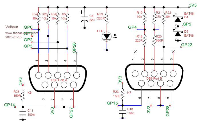 The analog joystick support (port B) uses the A/D convertors on GP26,27,28, but these can also duplicate as digital pins. The AtARI joysticks have switches, and individual switches can be read from MMBasic (interrupt even) easily. The NES controllers that are also target to be supported are serial (SPI) devices. The NES controller is a CD4021 (chapter 9), the SNES controller is a 16 bit version (2xCD4021), or similar. PIO could be of great help in doing the serial interface to the (S)NES controller. We could easily port the code from chapter 9 for port A and port B.... The code we made was configured in the PIO configuration. 1 piece of code, 2 different configurations, and we have 2 NES controller interfaces. Easy peasy... No Lets look at the connectors. The NES game controllers use a 9 pin sub-D connector with pinout: pin 2 = DATA pin 3 = LOAD pin 4 = CLOCK pin 6 = Vcc pin 8 = GND For the PIO configuration this will result in: PORTA: GP1 = DATA ------- IN group GP2 = LOAD ------- SET group GP3 = CLOCK ------ SET group PORTB: GP4 = DATA -------- IN group GP5 = LOAD -------- SEt group GP22 = CLOCK <------oops does not fit int he SET group, (5 pins max). Looking at the pinout, PORTA is a simple re-configuration of the code we used in chapter 9. But PORT B can not. The clock line (GP22) cannot be combined with the SET group that GP5 is in. In the ZIP provided later you can see a solution for CD4021 using SIDE SET. But for the SIDE SET, also a group size of maximum 5 (sacrificing all DELAY fields) is possible. A solution was found in using both SET and SIDE SET groups in a mix. control LOAD from the SET group, and CLOCK from the SIDE SET group. PORTA: GP1 = DATA ------- IN group GP2 = LOAD ------- SET group GP3 = CLOCK ------ SIDE SET group PORTB: GP4 = DATA -------- IN group GP5 = LOAD -------- SEt group GP22 = CLOCK <------SIDE SET group Below example shows the solution code. The code is well documented, so it should be no problem to understand what the code does. The only complexity is that the SIDE SET pin must be made output. For port B that cannot be done with a SET command (can do GP5,6,7,8,9, but not 22). We have discussed a way to do it in chapter 10: Use the OSR (output shift register) to shift a logic "1" into the PINCTRL register. This "trick" can only work when GP22 is part of the OUT group. So despite that we are not using serial shift out, we have to configure the OUT group. Note LOAD is called "latch" in below program. 'PIONES16 - PIO SPI for SNES controller 'VGApicomiteGAME board revision 1.4 'Shrink version (both stamemachines run same code) '-------------------------------- IO pin configuration ------------------------- 'pin asignment K8/sm0 K7/sm1 'data (in) � � gp1 � �gp4 'latch (out) � gp2 � �gp5 'clk (out) � � gp3 � �gp22 'reserve pins for PIO1 SetPin gp1,pio1:SetPin gp2,pio1:SetPin gp3,pio1 �'sm0 SetPin gp4,pio1:SetPin gp5,pio1:SetPin gp22,pio1 'sm1 'power the 2 ports K8 and K7 if needed SetPin gp14,dout:Pin(gp14)=1 SetPin gp15,dout:Pin(gp15)=1 '--------------------------------- PIO configuration -------------------------- 'PIO1 execute frequency f=200000 � '200kHz to achieve same responsiveness as 100kHz 8 bit controller 'note: the PIO program for both PIO's is the same, only the IO definition 'in the pinctrl register is different. The statemachines actually run same code 'pio config PIO1 sm0 s0=PIO(shiftctrl 0,0,0,0,0,1) � � � � 'default with IN shift left, OUT shift right p0=Pio(pinctrl 1,1,1,GP1,GP3,GP2,GP3) �'GP1=IN base GP2=SET GP3=OUT/SIDESET 'pio config PIO1 sm1 s1=PIO(shiftctrl 0,0,0,0,0,1) � � � � �'default with IN shift left, OUT shift right p1=Pio(pinctrl 1,1,1,GP4,GP22,GP5,GP22) 'GP4=IN base, GP5=SET GP22=OUT/SIDESET '------------------------------ PIO program (comment) ------------------------- 'pio1 sm0 program, identical code for sm0 and sm1, clock is side set pin 'adr/instr/comment '0 E081 'set pindir latch, out � � [side 0] '1 E000 'set latch low � � � � � � [side 0] '2 A0EB 'MOV null inverted to OSR �[side 0] '3 6081 'OUT 1 bit OSR to pindirs �[side 0] set clock output '4 E001 'latch high � � � � � � � �[side 0] latch pulse '5 E000 'latch low � � � � � � � � [side 0] '6 E02F 'load X with value 15 � � �[side 0] �<---------SNES = 15, NES = 7 '7 A0C3 'mov NULL to ISR � � � � � [side 0] '8 4001 'shift 1 bit data in ISR � [side 0] '9 1048 'JMP X-- to &h8 � � � � � �[side 1] this is the clock pulse 'A 8000 'push ISR � � � � � � � � �[side 0] 16 bits to fifo 'B 0004 'jmp to &h4 � � � � � � � �[side 0] next cycle '&h0C....&h1F not used '------------------------- END PIO program (comment) -------------------------- 'pio1 program in data statements Dim a%(7)=(&h6081A0EBE000E081,&hA0C3E02FE000E001,&h0004800010484001,0,0,0,0,0) 'program and start the PIO1 state machines PIO program 1,a%() � � �'program PIO1 PIO init machine 1,0,f,p0,,s0,0 � � � 'init sm0 from address &h00 PIO init machine 1,1,f,p1,,s1,0 � � � 'init sm1 from address &h00 (same code) PIO start 1,0 � � � � � � � � � � � � 'start PIO1 sm0 PIO start 1,1 � � � � � � � � � � � � 'start PIO1 sm1 '------------------------------ MAIN level ----------------------------------- Print "running" dim h%(4) 'read the FIFO's that contain the NES controller keys Do PIO read 1,0,5,h%() 'read from FIFO sm0 Print Hex$(65535-h%(4)), 'print value PIO read 1,1,5,h%() 'read from FIFO sm1 Print Hex$(65535-h%(4)) 'print value Pause 100 Loop 'While Inkey$="" End Note that this version was created 1 year ago, and could be optimized more with the knowledge we have today (using .wrap). But the code would have been so much simpler when the PORTA and PORTB pins where connected differently. And that is the motto for this appendix. Plan PIO use when creating a circuit diagram. Edited 2023-01-15 20:32 by Volhout PicomiteVGA PETSCII ROBOTS |
||||
| matherp Guru Joined: 11/12/2012 Location: United KingdomPosts: 8569 |
Have you had a chance to play with the interrupts yet? I'm pretty confident on the receive interrupt. Less so on the transmit which I'm not convinced of the utility |
||||
| Volhout Guru Joined: 05/03/2018 Location: NetherlandsPosts: 3496 |
I've been distracted, but it is on my list to do.... I guess you know this: next weekend my wife has birthday... Preparations and shopping. And no free evening to really do things (build HW and code). Volhout EDIT: a quick look makes me worry. I think it does not work as planned. Edited 2023-01-16 08:07 by Volhout PicomiteVGA PETSCII ROBOTS |
||||
disco4now Guru Joined: 18/12/2014 Location: AustraliaPosts: 843 |
A question on when SETPIN is required to disconnect the pin from the ARM and connect to PIO. My initial understanding: *** These require the SETPIN pinno,PIOx command *** Pins used by SET Pins used by OUT Pins used by SIDESET *** SETPIN is NOT required for pins referenced by: **** JMP PIN target i.e. pin defined in PIO (EXECCTRL ... function) IN GPIO x x is absolute pin number GP0-29) IN PIN x x is index added to IN_BASE in PIO(PINCTRL ... function WAIT [0|1] GPIO x is absolute pin number GP0-29) WAIT [0|1] PIN x is index added to IN_BASE in PIO(PINCTRL ... function Latest F4 Latest H7 |
||||
| phil99 Guru Joined: 11/02/2018 Location: AustraliaPosts: 1773 |
If I have understood the lessons only pins used for PIO output need to be assigned to PIO. PIO can read any pin regardless of whether it is set for PIO use, MMBasic use (in or out) or not set at all. Not sure about pins set for AIN. |
||||
| Pluto Guru Joined: 09/06/2017 Location: FinlandPosts: 328 |
Pins used by IN also needs to be disconnected from ARM (assigned to PIO). Example |
||||
| Volhout Guru Joined: 05/03/2018 Location: NetherlandsPosts: 3496 |
Honestly, I would need to try. Normally I would assign pins to PIO that belong to PIO. Since you are not sure how MMBasic will behave if a pin does not have an assignment. But I know that there are occasions where a pin used as an input by PIO (JMP / WAIT etc) works without assignment. For conditional JMP it is even explicitly stated in the chip manual. You are all students that are going further than you teacher ever went. Thank you for teaching me. I am learning from this. Thank you, Volhout PicomiteVGA PETSCII ROBOTS |
||||
| Pluto Guru Joined: 09/06/2017 Location: FinlandPosts: 328 |
I am struggling with the PIO command IRQ (RP2040 datasheet p327). Tried to understand the logics of calculating the INDEX. The datasheet gives 2 examples: My calculation gives the same results.  ...But, when listing the results of all combinations of state machines and interrupt flags, the same INDEX codes appear for various (unlogical) combinations.  sm= 0 flag= 0 Index: &h10 &b10000 sm= 0 flag= 1 Index: &h11 &b10001 sm= 0 flag= 2 Index: &h12 &b10010 sm= 0 flag= 3 Index: &h13 &b10011 sm= 0 flag= 4 Index: &h14 &b10100 sm= 0 flag= 5 Index: &h15 &b10101 sm= 0 flag= 6 Index: &h16 &b10110 sm= 0 flag= 7 Index: &h17 &b10111 sm= 1 flag= 0 Index: &h11 &b10001 sm= 1 flag= 1 Index: &h12 &b10010 sm= 1 flag= 2 Index: &h13 &b10011 sm= 1 flag= 3 Index: &h10 &b10000 sm= 1 flag= 4 Index: &h15 &b10101 sm= 1 flag= 5 Index: &h16 &b10110 sm= 1 flag= 6 Index: &h17 &b10111 sm= 1 flag= 7 Index: &h14 &b10100 sm= 2 flag= 0 Index: &h12 &b10010 sm= 2 flag= 1 Index: &h13 &b10011 Example from datasheet. OK sm= 2 flag= 2 Index: &h10 &b10000 sm= 2 flag= 3 Index: &h11 &b10001 Example from datasheet. OK sm= 2 flag= 4 Index: &h16 &b10110 sm= 2 flag= 5 Index: &h17 &b10111 sm= 2 flag= 6 Index: &h14 &b10100 sm= 2 flag= 7 Index: &h15 &b10101 sm= 3 flag= 0 Index: &h13 &b10011 sm= 3 flag= 1 Index: &h10 &b10000 sm= 3 flag= 2 Index: &h11 &b10001 sm= 3 flag= 3 Index: &h12 &b10010 sm= 3 flag= 4 Index: &h17 &b10111 sm= 3 flag= 5 Index: &h14 &b10100 sm= 3 flag= 6 Index: &h15 &b10101 sm= 3 flag= 7 Index: &h16 &b10110 > 'PROBLEM WITH PIO IRQ. How to calculate the IRQ Index? P.327-328 in RP2040 datasheet. 'The 3 LSBs specify an IRQ index from 0-7. This IRQ flag will be set/cleared depending on 'the Clear bit. 'If the MSB is set, the state machine ID (0�3) is added to the IRQ index, by way of 'modulo-4 addition on the two LSBs. For example, state machine 2 with a flag value of '0x11 will raise flag 3, and a flag value of 0x13 will raise flag 1. ' flag=0 'flags raised sm=0 'state machine FOR sm=0 to 3 FOR flag=0 to 7 NewIndex Print "sm=";sm," flag=";flag," Index: &h";HEX$(Index); " &b";BIN$(index,5) Next flag next sm end SUB NewIndex index0=&b10000+flag 'index before Modulo 4 addition is done 'print "index0: &b";bin$(index0,5) TwoLSBs= index0 and &b00011 'two LSBs for Modulo-4 addition. 'Print "TwoLSBs: &b";bin$(TwoLSBs,2) index1=index0-TwoLSBs ' 'Print "Mod4add(sm,TwoLSBs):";Mod4add(sm,TwoLSBs);" &b";bin$(Mod4add(sm,TwoLSBs),5) 'NewTwoLSBs=Mod4add(sm,TwoLSBs) and &b00011 NewTwoLSBs=Mod4add(sm,TwoLSBs) Index=index1+NewTwoLSBs 'print "Index: &h";HEX$(index);" &b";bin$(index,5) end sub FUNCTION Mod4add (a,b) as integer Mod4add=(a+b) MOD 4 end function .....Still confused, but at a higher level. |
||||
| Volhout Guru Joined: 05/03/2018 Location: NetherlandsPosts: 3496 |
Hi Pluto, I have never used interrupts in the PIO. So I cannot help you with this. When Peter and I solve the MMBasic interrupt on FIFO I can look at it, maybe I see somthing you overlooked. Again ... you are ahead of me... Volhout PicomiteVGA PETSCII ROBOTS |
||||
| Volhout Guru Joined: 05/03/2018 Location: NetherlandsPosts: 3496 |
@Peter, The interrupt from PIO INTERRUPT a,b,c,TX_INT does not work as I expected. Look at below code. This code polls the TX_FULL fifo flag (bit 16) in fstab to see if it can write new code into the fifo. When it sees there is room, it writes a new value. On LED's connected to GP1...5 you can see new data is provided every 1 second (the trigger to PULL in the PIO through GP0). ' demo program to demonstrate the use of the PIO interrupt ' the PIO is programmed to pull 1 word from FIFO at every rising edge of the GP0 pin. ' the LSB 5 bits are shown on GP1..GP5 (diagnostics) ' the GP0 pin is controlled from MMBasic in this demo, but could also be driven from ' an external source. � '-------------------------------- PIO state machine ----------------------------------- � 'PIO clear, and attach pins to PIO 1 �pio clear 1 �setpin gp1,pio1 �setpin gp2,pio1 �setpin gp3,pio1 �setpin gp4,pio1 �setpin gp5,pio1 � � 'the PIO program 'address � �code � �mnemonics � � � � � � comment ' �0 � � �E09F � � �SET pindirs &b11111 � GP1..GP5 out ' �1 � � �2000 � � �WAIT GP0=0 � � � � � �wait for external trigger on GP0 to pull ' �2 � � �2080 � � �WAIT GP0=1 ' �3 � � �8080 � � �PULL noblock � � � � �pulls data off fifo ' �4 � � �6005 � � �OUT OSR > pins 5 � � �shift 5 bits to GP1..5 pins ' �5 � � �0001 � � �JMP 1 � � � � � � � � repeat � �pio program line 1,0,&hE09F �pio program line 1,1,&h2000 �pio program line 1,2,&h2080 �pio program line 1,3,&h8080 �pio program line 1,4,&h6005 �PIO program line 1,5,&h0001 � � 'write the configuration, running 1MHz �f=1e6 �p=pio(pinctrl 0,5,5,gp0,,gp1,gp1) � �'pins GP1...GP5 = out, GP0 = in ' �s=PIO(shiftctrl 0,0,0,0,1,1) � � � �'default value ' �e=PIO(execctrl gp0,0,31) � � � � � �'default value: wrap defaults, GP0 = cond JMP pin ' �PIO init machine 1,0,f,p,e,s,0 � � �'PIO 1 SM 0 start adress = 0 �PIO init machine 1,0,f,p,,,0 � � � � 'PIO 1 SM 0 start adress = 0 � � � '-------------------------------- MMBasic MAIN --------------------------------------- � 'Halt the PIO from GP0 from MMBasic before it fills the FIFO out of control �setpin gp0,dout �pin(gp0)=0 � 'variables �dim d%=0 � 'start the pio1 code, state machine 1.0 will be waiting for a rising edge on the GP0 pin 'then it will pull 1 word from fifo. Then it will wait for the falling edge. The cycle repeats. �PIO start 1,0 � 'interrupt format PIO INTERRUPT PIO,SM,RX_SUB,TX_SUB ' �PIO interrupt 1,0,0,FeedFifo � 'freguently PIO pull data from the fifo �Settick 1000,PullFifo � � 'Main: interrupt free loop polling the NOT TX_FULL flag in FSTAT �do � �'wait until there is at least 1 free word in fifo � �do � � �'nothing � �loop while (pio(fstat 1) and 2^16) � � � �'fill fifo with 1 word of data � �FeedFifo � � �loop � end � � � '----------------------------------- SUBS --------------------------------------- � 'in this sub write 1 word to the Fifo. We can expand that to write more data until 'the fifo is full by repeated write and check of the fifo full flag. SUB FeedFifo �d%=d%+1 �if d%=32 then d%=0 �PIO write 1,0,1,d% �print "%"; end sub � 'in this sub we toggle the GP0 pin to force the PIO to fetch data from the FIFO sub PullFifo �pin(gp0)=1:pause 1:pin(gp0)=0:pause 1 end sub After RUN you see a very quick filling of the fifo (4 words) and from there a repeat whenever there is room in fifo. Now, when I replace the polling in the main loop by the PIO INTERRUPT, the interrupt routine is never called (no "%" is printed). So not a single word is written to fifo. Something is not okay here... ' demo program to demonstrate the use of the PIO interrupt ' the PIO is programmed to pull 1 word from FIFO at every rising edge of the GP0 pin. ' the LSB 5 bits are shown on GP1..GP5 (diagnostics) ' the GP0 pin is controlled from MMBasic in this demo, but could also be driven from ' an external source. � '-------------------------------- PIO state machine ----------------------------------- � 'PIO clear, and attach pins to PIO 1 �pio clear 1 �setpin gp1,pio1 �setpin gp2,pio1 �setpin gp3,pio1 �setpin gp4,pio1 �setpin gp5,pio1 � � 'the PIO program 'address � �code � �mnemonics � � � � � � comment ' �0 � � �E09F � � �SET pindirs &b11111 � GP1..GP5 out ' �1 � � �2000 � � �WAIT GP0=0 � � � � � �wait for external trigger on GP0 to pull ' �2 � � �2080 � � �WAIT GP0=1 ' �3 � � �8080 � � �PULL noblock � � � � �pulls data off fifo ' �4 � � �6005 � � �OUT OSR > pins 5 � � �shift 5 bits to GP1..5 pins ' �5 � � �0001 � � �JMP 1 � � � � � � � � repeat � �pio program line 1,0,&hE09F �pio program line 1,1,&h2000 �pio program line 1,2,&h2080 �pio program line 1,3,&h8080 �pio program line 1,4,&h6005 �PIO program line 1,5,&h0001 � � 'write the configuration, running 1MHz �f=1e6 �p=pio(pinctrl 0,5,5,gp0,,gp1,gp1) � �'pins GP1...GP5 = out, GP0 = in ' �s=PIO(shiftctrl 0,0,0,0,1,1) � � � �'default value ' �e=PIO(execctrl gp0,0,31) � � � � � �'default value: wrap defaults, GP0 = cond JMP pin ' �PIO init machine 1,0,f,p,e,s,0 � � �'PIO 1 SM 0 start adress = 0 �PIO init machine 1,0,f,p,,,0 � � � � 'PIO 1 SM 0 start adress = 0 � � � '-------------------------------- MMBasic MAIN --------------------------------------- � 'Halt the PIO from GP0 from MMBasic before it fills the FIFO out of control �setpin gp0,dout �pin(gp0)=0 � 'variables �dim d%=0 � 'start the pio1 code, state machine 1.0 will be waiting for a rising edge on the GP0 pin 'then it will pull 1 word from fifo. Then it will wait for the falling edge. The cycle repeats. �PIO start 1,0 � 'interrupt format PIO INTERRUPT PIO,SM,RX_SUB,TX_SUB �PIO interrupt 1,0,0,FeedFifo � 'freguently PIO pull data from the fifo �Settick 1000,PullFifo � � 'Main: loop doing nothing while interrupt and FeedFifo do the job �do � �'wait here and let the process unfold � �print "."; � �Pause 100 � � �loop � end � � � '----------------------------------- SUBS --------------------------------------- � 'in this sub write 1 word to the Fifo. We can expand that to write more data until 'the fifo is full by repeated write and check of the fifo full flag. SUB FeedFifo �d%=d%+1 �if d%=32 then d%=0 �PIO write 1,0,1,d% �print "%"; end sub � 'in this sub we toggle the GP0 pin to force the PIO to fetch data from the FIFO sub PullFifo �pin(gp0)=1:pause 1:pin(gp0)=0:pause 1 end sub Edited 2023-01-16 20:43 by Volhout PicomiteVGA PETSCII ROBOTS |
||||
| Volhout Guru Joined: 05/03/2018 Location: NetherlandsPosts: 3496 |
@Peter, Reason I proposed to use the FSTAT TX_FULL (and not TX_EMPTY) flag is becuase of potential latency in the main code, it take time before we actually start feeding the FIFO. In that time another word could have been fetched from FIFO by the PIO. So we can accept up to 3 words latency in the MMBasic code. Regards, Harm PicomiteVGA PETSCII ROBOTS |
||||
| matherp Guru Joined: 11/12/2012 Location: United KingdomPosts: 8569 |
I don't use TX_EMPTY, I effectively use TX_NOT_FULL when TX_FULL last time. i.e. it is supposed to interrupt whenever there is space in the FIFO and it was previously full. HOWEVER, even if it worked, I'm still very unconvinced of the utility of this at all If you need to feed fast then there is much less overhead polling PIO(FLEVEL or PIO(FSTAT than triggering an interrupt. And if you are feeding slowly then presumably the FIFO will never be full anyway |
||||
| Pluto Guru Joined: 09/06/2017 Location: FinlandPosts: 328 |
It is never good when the wagon comes ahead of the horse. |
||||
| Volhout Guru Joined: 05/03/2018 Location: NetherlandsPosts: 3496 |
Maybe that causes it. A pristine PIO will have empty FIFO's. So the interrupt will not trigger to start filling the FIFO. This can only work if someone brute force fills the fifo with 4 entries first (or 8 when linked fifo's). Volhout PicomiteVGA PETSCII ROBOTS |
||||
| matherp Guru Joined: 11/12/2012 Location: United KingdomPosts: 8569 |
Just looked at your code again. You are assuming that you will get an interrupt whenever the FIFO is not full. Whereas I am interrupting when the FIFO goes from full to not full. You need to fill the FIFO to start the process running. Code below works perfectly ' demo program to demonstrate the use of the PIO interrupt ' the PIO is programmed to pull 1 word from FIFO at every rising edge of the GP pin. ' the LSB 5 bits are shown on GP1..GP5 (diagnostics) ' the GP0 pin is controlled from MMBasic in this demo, but could also be driven from ' an external source. '-------------------------------- PIO state machine ----------------------------------- 'PIO clear, and attach pins to PIO 1 PIO clear 1 SetPin gp1,pio1 SetPin gp2,pio1 SetPin gp3,pio1 SetPin gp4,pio1 SetPin gp5,pio1 'the PIO program 'address code mnemonics comment ' 0 E09F SET pindirs &b11111 GP1..GP5 out ' 1 2000 WAIT GP0=0 wait for external trigger on GP0 to pull ' 2 2080 WAIT GP0=1 ' 3 8080 PULL noblock pulls data off fifo ' 4 6005 OUT OSR > pins 5 shift 5 bits to GP1..5 pins ' 5 0001 JMP 1 repeat PIO program line 1,0,&hE09F PIO program line 1,1,&h2000 PIO program line 1,2,&h2080 PIO program line 1,3,&h8080 PIO program line 1,4,&h6005 PIO program line 1,5,&h0001 'write the configuration, running 1MHz f=1e6 p=Pio(pinctrl 0,5,5,gp0,,gp1,gp1) 'pins GP1...GP5 = out, GP0 = in ' s=PIO(shiftctrl 0,0,0,0,1,1) 'default value ' e=PIO(execctrl gp0,0,31) 'default value: wrap defaults, GP0 = cond JMP pin ' PIO init machine 1,0,f,p,e,s,0 'PIO 1 SM 0 start adress = 0 PIO init machine 1,0,f,p,,,0 'PIO 1 SM 0 start adress = 0 '-------------------------------- MMBasic MAIN --------------------------------------- 'Halt the PIO from GP0 from MMBasic before it fills the FIFO out of control SetPin gp0,dout Pin(gp0)=0 'variables Dim d%=0 'start the pio1 code, state machine 1.0 will be waiting for a rising edge on the GP0 pin 'then it will pull 1 word from fifo. Then it will wait for the falling edge. The cycle repeats. 'interrupt format PIO INTERRUPT PIO,SM,RX_SUB,TX_SUB PIO interrupt 1,0,,FeedFifo PIO start 1,0 Do feedfifo Loop Until Pio(flevel 1,0,TX)=4 'freguently PIO pull data from the fifo SetTick 1000,PullFifo 'Main: interrupt free loop polling the NOT TX_FULL flag in FSTAT Do Loop End '----------------------------------- SUBS ------------------------------------- -- 'in this sub write 1 word to the Fifo. We can expand that to write more data until 'the fifo is full by repeated write and check of the fifo full flag. Sub FeedFifo d%=d%+1 If d%=32 Then d%=0 PIO write 1,0,1,d% Print "%"; End Sub 'in this sub we toggle the GP0 pin to force the PIO to fetch data from the FIFO Sub PullFifo Pin(gp0)=1:Pause 1:Pin(gp0)=0:Pause 1 End Sub |
||||
| Volhout Guru Joined: 05/03/2018 Location: NetherlandsPosts: 3496 |
Well, it is the only time the horse can see what it is pulling....;) PicomiteVGA PETSCII ROBOTS |
||||
