
|
|
Forum Index : Microcontroller and PC projects : PicoMite: what the monkey made
| Author | Message | ||||
| Turbo46 Guru Joined: 24/12/2017 Location: AustraliaPosts: 1641 |
Thanks Peter, You are right of course but how do you know when a manual is updated? I did download it some time ago to see if an error that I reported was fixed, it hadn't so I discarded it and continued to use the one downloaded with the firmware. Bill Keep safe. Live long and prosper. |
||||
| thwill Guru Joined: 16/09/2019 Location: United KingdomPosts: 4308 |
And I'm very grateful to Bill for carrying the audio baton to TBS for me. Correct, I have modules using the PAM8403 (https://www.ebay.co.uk/itm/265562046052) and MAX98306 (https://www.aliexpress.com/item/4001137950571.html) chips on the way. <shrugs shoulders> The next prototype (on 100x100 perfboard) will use one of those modules (assuming either works). If I move forward to a PCB then my current thinking is to avoid the prebuilt modules and instead put SMD directly on the PCB for filter, amp (and battery charging circuit) and then get JLPCB to do the work for me. Of course there is also the question of whether the board should also have a headphone jack ... presumably that requires different amplification ? Anyway it's all just "playing" so please only spend your time on it if you are interested. Note that the "smart" thing for me to do would actually be to (try to) port the PicoMite firmware to the PicoSystem hardware (https://shop.pimoroni.com/products/picosystem), but that is just another programming project and I have more than enough of those on my backlog already. Best wishes, Tom Edited 2022-12-21 19:26 by thwill MMBasic for Linux, Game*Mite, CMM2 Welcome Tape, Creaky old text adventures |
||||
| Mixtel90 Guru Joined: 05/10/2019 Location: United KingdomPosts: 7889 |
I've found some little speakers at Bitsbox. 16mm dia and 20mm dia.. The 16mm one has a lumpy response that starts at about 1kHz. The 20mm isn't much better but starts at about 700Hz. Either would probably be fine in this, I think. I've been having a look at fitting it into the Hammond 1593 box and I'm pretty sure it's possible even using modules and not much SMD. I had to use smaller buttons (the tops are 9mm dia) and I've still not sorted anything out for Select and Start. The buttons are the KS01 type. which I've used before and don't seem too bad. You can't get the display right to the back wall of the box because of internal pillars, which is what limits the button area.The buttons are on a daughter board, raised up from the main board. This gives some space underneath it for other bits and gets the buttons up to the top. Stereo headphones won't work with any of the bridged output modules as there's no common, i.e. probably any that will give 80mW upwards from 3.3V I'm considering using a PAM module and fitting a headphone jack though, but it would only be on one channel (which does seem possible). I've hit a snag though in that I've not found a way to automatically detect when headphones are plugged in so that the PicoMite can be told to change its output from stereo to mono and mute the other channel. Edited 2022-12-21 20:48 by Mixtel90 Mick Zilog Inside! nascom.info for Nascom & Gemini Preliminary MMBasic docs & my PCB designs |
||||
| thwill Guru Joined: 16/09/2019 Location: United KingdomPosts: 4308 |
You are a fortnight late, I have already received that pair of speakers from BitsBox, I just don't have an amp to drive them with yet. I'd been looking at those too as the basic ones I used on the above prototype are a bit too clicky. Best wishes, Tom MMBasic for Linux, Game*Mite, CMM2 Welcome Tape, Creaky old text adventures |
||||
| Mixtel90 Guru Joined: 05/10/2019 Location: United KingdomPosts: 7889 |
Trust me to be late..... � :) The KS01 are a bit clicky and need a little pressure to operate, but they aren't bad. Wath out - the pins are on 5mm pitch so be gentle if putting them into veroboard. LM4917 looks like a promising amp, but only 95mW into 16R or 82mW into 32R. 8R not suitable. Edited 2022-12-21 20:57 by Mixtel90 Mick Zilog Inside! nascom.info for Nascom & Gemini Preliminary MMBasic docs & my PCB designs |
||||
| phil99 Guru Joined: 11/02/2018 Location: AustraliaPosts: 2626 |
To use headphones on a bridge amplifier connect ground to ground and output L+ to headphone L via a 47uF cap. (+ to L+) same for right. You won't get the maximum volume as only one side of the bridge is being used, but in headphones it will still be enough. |
||||
| Volhout Guru Joined: 05/03/2018 Location: NetherlandsPosts: 5072 |
@Phill, This is what used to be in the walkmans. One or 2 tiny speakers and a stereo headset output.  As for the input filter for up to 4 a 5 kHz, you will get decent performance using this (connect 330 ohm to PWM, R4 (10k) will be the volume potmeter. The maximum output voltage is 2Vpp.  Volhout Edited 2022-12-21 22:20 by Volhout PicomiteVGA PETSCII ROBOTS |
||||
| Mixtel90 Guru Joined: 05/10/2019 Location: United KingdomPosts: 7889 |
Oh, I like that solution... :) Mick Zilog Inside! nascom.info for Nascom & Gemini Preliminary MMBasic docs & my PCB designs |
||||
| thwill Guru Joined: 16/09/2019 Location: United KingdomPosts: 4308 |
Thanks @Volhout, but is this before the amp, or after the amp ... I assume before, in which case where does this "330 ohm to PWM" connect ? Also do you make it a matter of pride to use a different capacitor that I don't have in every design  . .Best wishes, Tom MMBasic for Linux, Game*Mite, CMM2 Welcome Tape, Creaky old text adventures |
||||
| Volhout Guru Joined: 05/03/2018 Location: NetherlandsPosts: 5072 |
In case you have 47nf, 15nf and 4.7nf...that will also work.... Volhout PicomiteVGA PETSCII ROBOTS |
||||
| Mixtel90 Guru Joined: 05/10/2019 Location: United KingdomPosts: 7889 |
Tom sent me the schematic. ;) Mick Zilog Inside! nascom.info for Nascom & Gemini Preliminary MMBasic docs & my PCB designs |
||||
| thwill Guru Joined: 16/09/2019 Location: United KingdomPosts: 4308 |
... especially since it was your PicoMite Backpack schematic that I cribbed from  . .Best wishes, Tom Edited 2022-12-22 05:45 by thwill MMBasic for Linux, Game*Mite, CMM2 Welcome Tape, Creaky old text adventures |
||||
| Mixtel90 Guru Joined: 05/10/2019 Location: United KingdomPosts: 7889 |
See? That Backpack has a lot of mysterious stuff in it. :) Mick Zilog Inside! nascom.info for Nascom & Gemini Preliminary MMBasic docs & my PCB designs |
||||
| thwill Guru Joined: 16/09/2019 Location: United KingdomPosts: 4308 |
Hmm, whilst EasyEDA seemed to be fine for knocking out a schematic without caring very much about what "physical" components it wanted to use, when I try to use it in the context of an actual PCB it doesn't make much sense to me ... wtf is an R_AXIAL-0.5_EU vs. an R_AXIAL-1.2_EU ... I'm guessing it is something to do with the pad spacing for the resistor but what is it measuring in ? Perhaps I need to be thinking about Sprint Layout (6) since I am more likely to be able to lean on you fine gentlemen for support ... or perhaps I am simply out of my depth and need months of apprenticeship/education ? Is SL6 something I buy, or is it free ? I can't seem to identify the actual developer/vendor online though all sorts of (not entirely reliable looking) places seems to have it available. Any advice ? Best wishes, Tom Edited 2022-12-22 10:49 by thwill MMBasic for Linux, Game*Mite, CMM2 Welcome Tape, Creaky old text adventures |
||||
bigmik Guru Joined: 20/06/2011 Location: AustraliaPosts: 2949 |
Hi Tom, If you want I can help you by looking at doing a PCB for you but I will do it in DEX (AutoTraxDEX). If you want to go down that path I will need the following: Schematic. Physical size of the PCB including any cutouts or holes. Layout and spacing plus location for the switches. Physical size of the major components i.e screen (don't worry about the Pico) Part numbers for the various switches would help me with sizes and pad layout etc. I, of course wont take any responsibility for any errors and I will send you the board layout in JPEG/PNG/PDF for your perusal first then when you are happy I will generate the Gerbers and send them to you. The board will remain yours to sell, distribute or whatever you want but I would like one for myself. Kind Regards Mick Mick's uMite Stuff can be found >>> HERE (Kindly hosted by Dontronics) <<< |
||||
| Turbo46 Guru Joined: 24/12/2017 Location: AustraliaPosts: 1641 |
@Tom, ABACOM are the people who make it. You can download a free demo version but it won't save anything. Otherwise 49.90 Euro. You can put capacitors in series or parallel for a temporary test setup if you like. @Volhout, Thanks for the filter. Do you think it should have AC coupling to the amplifier? Bill Keep safe. Live long and prosper. |
||||
| phil99 Guru Joined: 11/02/2018 Location: AustraliaPosts: 2626 |
"wtf is an R_AXIAL-0.5_EU vs. an R_AXIAL-1.2_EU " Just guessing, Resistor, axial leads, 0.5 Watts, European Standard Size. Resistor, axial leads, 1.2 Watts, European Standard Size. |
||||
| Mixtel90 Guru Joined: 05/10/2019 Location: United KingdomPosts: 7889 |
I would recommend, if you are serious about doing PCBs using schematic capture, that you persevere with EasyEDA (or DesignSpark) Tom. A proper PCB design tool is far more flexible. The only problem is that they tend to have steepish learning curves (almost vertical if you want to design your own components for KiCad. :( It's incredibly powerful though.). Sprint Layout is a PCB drawing package, not really a PCB design tool. It has no schematic capture at all and can't import data from other programs. You can't even cut and paste stuff from one window to another. However, it's *very* easy to get going with and once you've collected a parts library together it can be very fast for simple layouts. It would be out of its depth on a complicated board. It's almost a specialised 2D CAD program in some ways, but without the positioning accuracy. It's also more expensive than DesignSpark! Mick Zilog Inside! nascom.info for Nascom & Gemini Preliminary MMBasic docs & my PCB designs |
||||
| Volhout Guru Joined: 05/03/2018 Location: NetherlandsPosts: 5072 |
The class D amplifier board thatw as referenced to before has 1uF input capacitors. AC coupling is on that board... Volhout PicomiteVGA PETSCII ROBOTS |
||||
| Mixtel90 Guru Joined: 05/10/2019 Location: United KingdomPosts: 7889 |
This needs quite a bit of tidying up. It's pretty much still work in progress, but now I'm happy that the bits will fit in the box. I'm not sure that going all SMD would gain much physically, although it would probably reduce assembly cost if several were being manufactured. I made the PicoMite surface mount anyway to save on height. There's no Reset button and the Boot button isn't accessible with the display fitted. The main PCB sits on additional 5mm spacers, giving a fraction over 10mm beneath it. That's sufficient to fit a 1500mAh LIPO battery in (8mm thick IIRC). There are no through-hole connections over it to cause damage. On top of the main PCB, the display is on 11mm spacers. These allow for the usual plug-in connectors. Also on top is the buttons daughter board on 6mm spacers. This would probably have to be hard wired as I'm not aware of a plug-in connector to fit this space off-hand (although something may be possible). I've still not sorted out button tops for Select & Start.  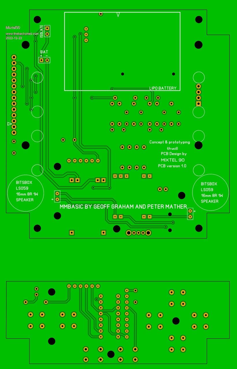 If anyone would like to have a play with this I can supply the SL6 file if Tom is happy for me to do so - it's his project, not mine. Mick Zilog Inside! nascom.info for Nascom & Gemini Preliminary MMBasic docs & my PCB designs |
||||
| The Back Shed's forum code is written, and hosted, in Australia. | © JAQ Software 2025 |
