
|
|
Forum Index : Electronics : Hopefully? Another 48vdc-240vac Toriod Inverter build.
| Author | Message | ||||
| KeepIS Guru Joined: 13/10/2014 Location: AustraliaPosts: 1401 |
Mike and Aaron, I also have stripped an Aurora that was given to me. The blue toroidal cores are the same physical size as the black, the black require less turns for the same inductance, which is why I used them instead. The numbers for all my cores come up with data sheets when searched on Google. The Ferrite E-core on it's own gets quite hot, it's seems fine in series with the toriodal ring choke. I think dropping the Ferrite inductance to 16uH helps with that and the combined two comes out at 31uH. BTW If the Aurora is the same as mine, it has a big beautiful Heat sink with a curved cover to enhance airflow through the fins, this is going on the back of my inverter cabinet and Mikes Inverter board will be mounted on that as a complete removable unit (Heat sink and Driver board). Blue: Bluetoriod.pdf Black data image below: 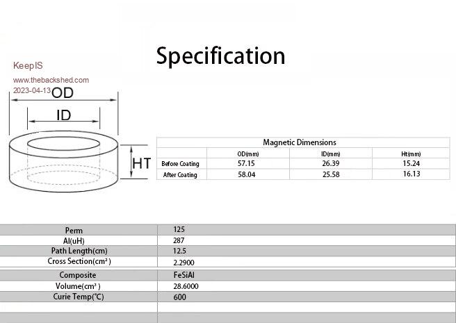 EDIT:You can't see it from the Cabinet photo but there is another a Big fan directly below the Transformer, same size as the one above it. That is a stage 3 fan for when the going gets tough in heatwave conditions Aircons running all day etc. The Fan above the toriod is offset slightly to push air around the transformer and bottom cabinet section. The Air is pulled into the Middle shelf on the RH side and exits the bottom of the cabinet through the Toriod. I don't like pulling crap that builds up "under" equipment cabinets into electronic gear. . Edited 2023-04-13 09:17 by KeepIS It's all too hard. Mike. |
||||
| Murphy's friend Guru Joined: 04/10/2019 Location: AustraliaPosts: 602 |
You may not like that, perhaps from personal experience, but this never happened in the years I have cooled my inverters by an air intake at the bottom of the cabinet. The outlet is at the top side to prevent dust falling in. My inverters: 1. they are located on a clean concrete floor (on castors). 2. the air intake & exit opening is screened with metal fly screen to keep bugs out. 3. the inverter heatsink, its orientation and the location of the toroid/ chokes ensure good heat transfer by natural convection. If you build the inverter enclosure with a sideways air flow then the fans run more often and you need more of them - I know that from my first inverter built that way. I see its your first inverter build, let me assure you, its a long learning curve  A tip; do not have any inside LED visible from the outside of the cabinet via some cooling opening. If you read back long enough in this forum, Oztules had a serious failure caused by moths finding a blue LED inside the inverter too attractive and clustered around it in big enough numbers to shorten something out  . . |
||||
| Murphy's friend Guru Joined: 04/10/2019 Location: AustraliaPosts: 602 |
A double stack of these black cores can also be found when stripping the chokes from a Latronics inverter - a picture of which is shown in another recent thread. Thes cores have a powdered iron material - not ferrite, when I looked at the spec sheet for the number on the cores. |
||||
| KeepIS Guru Joined: 13/10/2014 Location: AustraliaPosts: 1401 |
We have had this discussion before. Your workshop or location must be a lot cleaner than ours. It's unfortunate that's not the case here. This large workshop is used for many things that create threads, fibers, some dust and various other craft materials on the floors. However, like I said, the side fan is SILENT, as in, cannot be heard, so it's not that different then having natural convection flow through the cabinet from the bottom. The inverter is not outside, it's in a lined shed, no insects, although I should get around to removing the led as I didn't know it had one until I fitted it. I pulled the filter off the other day to change a connection, and it was still off when I took the photo. I don't know if I said they were Ferrite? if so that was a typo, so I assume that was just a general FYI comment. Yes composite of Iron with various amounts of Aluminum and Silicon. Finally, the heatsink will be on the outside rear of the Cabinet covering a cutout in the cabinet. Mikes inverter board will be mounted onto that 330mm X 300mm X 85mm heatsink and the cutout allows the heatsink and inverter board to be removed as a one piece unit. Obviously that will have convection cooling over the substantial fins which also have a removable airflow enhancing cover as part of the original design. . Edited 2023-04-13 16:23 by KeepIS It's all too hard. Mike. |
||||
| KeepIS Guru Joined: 13/10/2014 Location: AustraliaPosts: 1401 |
Just a bit of random info on the change to the Saturation tester and Chokes. I rewound the 10 stack Toriod ring choke and trimmed the connection leads. 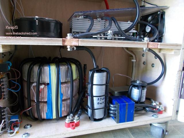 I realized that I needed to beef up the connection points on my Saturation tester as peak currents can reach over 1000A @ 100V, so any lead length inductance or slight loss in connection will skews the result when measuring low inductance chokes, especially the 10 Stack toriod with only a few turns and the two 16uH chokes. Yellow Trace: 500A Current clamp, rated to 700A but peaks around 1200A. First a ONE ohm resistor on the Saturation tester: 12.5A per division Sat tester voltage 100v 8 Vert divisions Result 100A 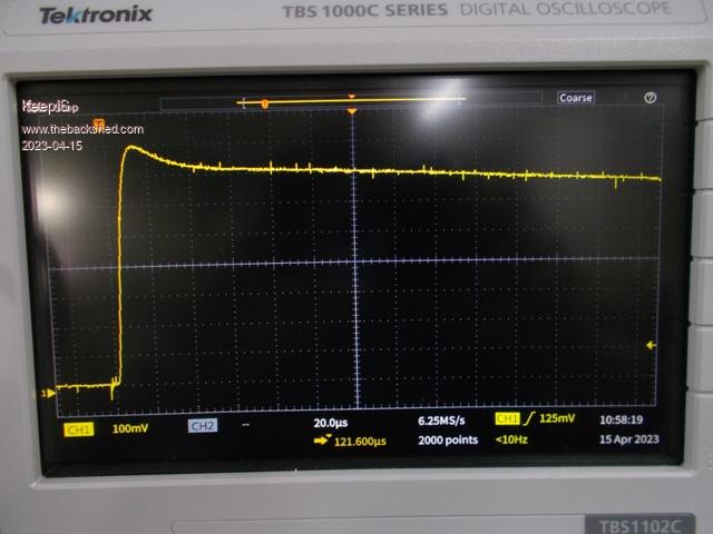 Yes, the trace discharge cycle does fall to zero. 37uH 10 stack toriod choke: Sat voltage 100V Vert div = 175A per division 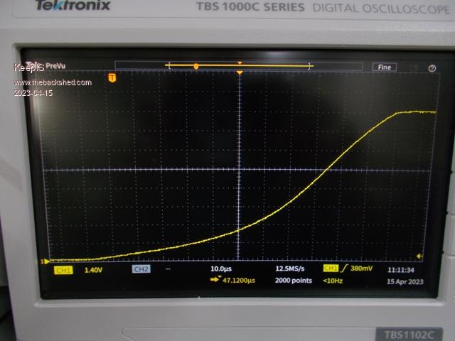 16uH Ferrite choke, gaped and 4 turns: Sat voltage 100V Vert div = 175A per division 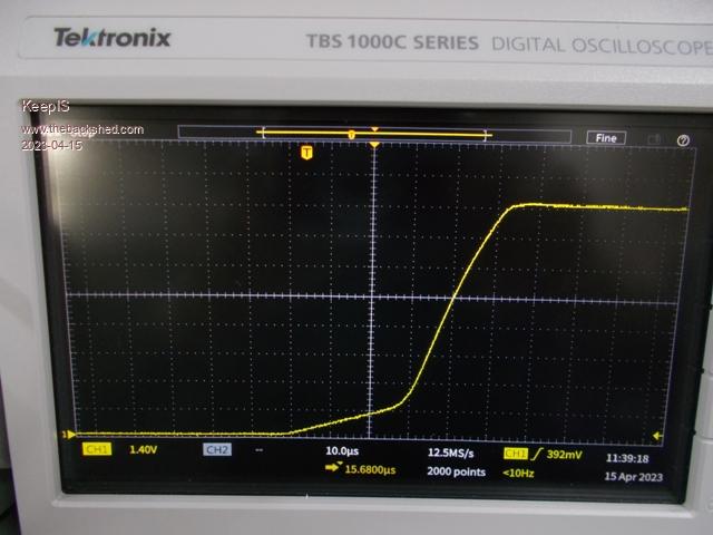 . Edited 2023-04-15 11:42 by KeepIS It's all too hard. Mike. |
||||
| KeepIS Guru Joined: 13/10/2014 Location: AustraliaPosts: 1401 |
Just for fun, a quick overlay combination of the last two choke displays, Ferrite E-Core and 10 stack toriod. BTW the Flattop may be the Current Sensor supply Rail limiting more then Cap voltage / current, both at the same point. Saturation tester @ 100V Vert div = 175A per division 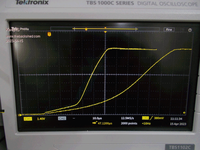 . Edited 2023-04-16 08:19 by KeepIS It's all too hard. Mike. |
||||
| KeepIS Guru Joined: 13/10/2014 Location: AustraliaPosts: 1401 |
As I was tidying up the transformer and Choke compartment of the Inverter, I decided to bite the bullet and wind a new 14 turn primary on the Transformer with heaver gauge wire, length of primary is 7 meters, using a hard rubber mallet and a heat gun to get the slack out of each bend on the 14 turns. So just as an FYI I have never weighed the transformer so: Transformer weight is 27.3kg Before winding the heavy primary. I originally wound it with a 28-240 voltage ratio and left it the same. I also re-tested base idle current over a wider range, also looking for a steep climb in current that might be an indication of saturation. I stopped at 280v AC output. I used a Variac to supply Low Voltage AC input to the 14T primary winding. AC in = AC out @ Power draw from AC in. 26.8v = 225v @ 13.6 watts 27.3v = 230v @ 14.5 watts 28.4v = 240v @ 16.0 watts 29.8v = 250v @ 18.0 watts 31.0v = 260v @ 19.0 watts 32.0v = 270v @ 22.7 watts 33.3v = 280v @ 26.0 watts With the Transformer connected to the inverter the total idle current is 27 watts, there is the data logger ("9" display screen), control board, 80v to 24v DC-DC supply for the big Contactor and other sensors, LEDs etc running from another 80V to 12v DC-DC converter all adding another 12 watts. The initial average night time 230v AC inverter Load is around 520 watts and drops off to around 150 watts once TV and sound system etc are switched off. It transitions between 150 watts and 350 watts at various times during the night with the two Fridge freezers, security lights being tripped (cats) path lights, and 6 security Cameras running/recording. Tested the heaver primary winding, the AC waveform under load was really impressive before but now it's also that good under huge startup loads. I ran the same test on Mains 240ac and I had to check that I was not still on the inverter. There is virtually no difference, I even turned the dam inverter off to be sure, because to me, that was just so crazy good that it couldn't be true. Looking at the AC waveform on a DSO while starting the Dust extractor, there was no change to the Sine wave, no funny kinks, no spikes just a good sine wave. The amplitude dropped very slightly, the only real indication of the huge Load. This is with a 2 second startup DC current draw consisting of a train of AC 500A (0 to 48v) transitions every 10ms on the DC input. However: I have also added that hybrid Ferrite/Toriod Choke, so I guess a combination of the Heavy primary and choke? Before this, the AC output had a good kink on one side and skewed a bit under that big load. 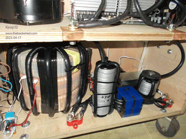 . Edited 2023-04-18 10:25 by KeepIS It's all too hard. Mike. |
||||
Revlac Guru Joined: 31/12/2016 Location: AustraliaPosts: 964 |
Looks good Mike, Back when playing with a large EI Transformer (it had multi taps) I also tried different primary voltages 28v to 25v I don't think it fired up on the 25v winding, perhaps something els I was doing but it was happy with 26v primary and 240vac secondary, had the lowest idle watts then. On the other Mad Inverter, the transformer was suitably wound but I did notice when running on a set of FLA Batteries, the Idle current would increase as the battery voltage increased to 58v during bulk charge, but it was very happy running at 54v or less. Measured the Aurora inverter heat sink 85X320X500, its a 5Kw unit. I have an 8 camera recording system and it's overnight consumption was more than expected, removed the HDD and installed a SSD, that dropped the power consumption dramatically, so that was worth the effort. Your choke arrangement works very well, Every inverter build here is different and as a few more builds get up and running it might show us if the choke setup is more customised for each different transformer or core materiel, we will find out as builds progress.  Cheers Aaron Off The Grid |
||||
| analog8484 Regular Member Joined: 11/11/2021 Location: United StatesPosts: 92 |
Can you summarize what you think the nominal power specs are of the latest system config? Is it 10kW with 20kW surge? |
||||
| KeepIS Guru Joined: 13/10/2014 Location: AustraliaPosts: 1401 |
Hi Aaron Yes for a given turns ratio, reducing output voltage by lowering the primary appears to take the toriod further away from idle saturation and I assume that eddy current loss is also reduced. Obviously in a conventional inverter at Idle, the VFB would hold the Toriod input voltage at same voltage needed to produce 230vac no matter what the battery voltage within the HI/LO cut off range limits, so any change in idle current with Battery voltage in my case is the Inverter Driver and the two SMPS I use drawing more current as the DC voltage drops, but power input does not really change. Absolutely, the choke for my single core Aerosharp was different to the requirements of the three stack core. I notice the value needed is also dependent on the turns ratio of the main Toriod, so when you think about the Secondary Cap value to resonate, the size of the primary wiring, the turns ratio and the variations in core material and secondary turns, overlapped or single wound and so on, there is a lot of scope to finding a good choke compromise to suite both the big startup currents and the everyday running current. Sorry to a bit vague here - But depends: Peak current/power or RMS. I tend to look at the peak specs of the FETs and so I'm interested in the Peak instantaneous currents/power they are exposed to, so in that context, around 23kW surge, but RMS power input for the biggest short term start load is around 12kW RMS surge. I don't know what the limit is, and I'm not sure I want to ever find out  Obviously the only real limitation for running Power is heat build up in the Toriod and chokes. I ran at almost 5kW with the smaller primary and chokes, so with heavy primary winding and choke modification consisting of rewinding with heavy wire and with less turns (more core), I think conservatively 5kW continuous. IMHO there is no doubt it can do a lot more if needed. Under that load the Toriod core temp was 40 deg and the FETs around 36 to 39 deg, a few deg from the same values running at 1kW, when output increased to 5kW, the fans started running and temps stayed within a few deg of 1kW. With the Heavy Primary, the Nasty industrial Air Compressor, not the toys units from the local hardware, causes a momentary very "low Hum" that is almost gone before it starts, 520A peak startup current is handled instantly. That's why I'm happy to have the chokes wound with a slightly smaller cable compared to the Transformer primary, and I don't worry about using two sets of big terminals to bolt the chokes into the system, it makes it easy to remove them when testing and the slight R-loss is, IMHO, a bit of a buffer for the FETs under sudden big shock loads. This inverter makes my off the shelf 5kW/10kW inverter look like a toy. . It's all too hard. Mike. |
||||
| KeepIS Guru Joined: 13/10/2014 Location: AustraliaPosts: 1401 |
A while back I posted a question about my Inverter AC waveform having a slightly flat top and mentioned the Mains AC was the same, I though I would post the DSO capture. In the past I went looking for older posts about Mains and AC out and found almost identical posts, although most had a very noticeable kinks in the waveform as well, but the flattish top was there. I could have saved myself a lot time if I had looked at the Mains AC powering the same full off grid load. I found the AC mains is the same and below is the capture. 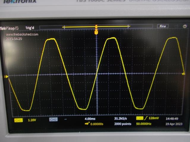 It's either the big Inverter Fridge freezer or some other newer inverter appliance. I still have to track this down just for my own curiosity. The inverter has been sitting around 3kW + for the past hour with a lot of workshop gear running on top of the normal daily loads and handling 8kW AC "startup" loads on top of that. IE: 500A DC held for 2 second of flywheel/fan spin up time. The only difference between this Mains AC screen shot and the Inverter AC running is the slightest pin point imperfection on the leading slope just after the minimum AC swing and the same pin point on the trailing slope just after the AC peak. FYI: I've been monitoring the Inverter AC for the past few days to see how it holds up under the massive peak load start currents of the workshop equipment, looking for any signs that might indicate a problem after beefing up the chokes and Toriod primary, but its been just perfect except for the slight top imperfection, which from the consensus of opinion is basically normal. . Edited 2023-04-20 18:34 by KeepIS It's all too hard. Mike. |
||||
| analog8484 Regular Member Joined: 11/11/2021 Location: United StatesPosts: 92 |
Yeah ... that's why I was thinking it could be a 10kW/20kW inverter. Given the number of MOSFET's and size of the transformer and chokes it looks a bit beefier than a Schneider XW PRO which is rated for 6.8kW/12kW but actually can run 9kW for 30 minutes. |
||||
| KeepIS Guru Joined: 13/10/2014 Location: AustraliaPosts: 1401 |
That is interesting, and I agree, I guess you can see that I'm trying to be conservative here, but it's just laughing at 5kW. After realizing that it really has no trouble starting 60A 230VAC loads, I decided to make a bigger and better multistage AC output filter, should have it fitted today. BTW: I think there is a huge advantage in splitting the secondary 260Vac winding across three toriods. A: One single layer of 1/3 the turns on each toriod across 3 toriods. Allowing heaver gauge wire to be used as your are winding Less wire through the thickness of only one core. B: Easier construction, not trying to work with the weight and depth of 3 cores at one time when winding a high turn secondary. C: The inner diameter of the Toriod still remains larger, therefore winding a heavy single primary through the 3 stacked cores was an easy 5 minute job for me. D: Better primary heat dissipation across 3 toriods with the added bonus of also allowing some air flow between each toriod (Each 1/3 secondary winding). I can not see a single negative in doing it this way. No increase in Idle current. No loss in efficiency. . It's all too hard. Mike. |
||||
| Revlac Guru Joined: 31/12/2016 Location: AustraliaPosts: 964 |
 I like this idea, trick is to find 2 or 3 the same (or close to it) to start with. Cheers Aaron Off The Grid |
||||
| KeepIS Guru Joined: 13/10/2014 Location: AustraliaPosts: 1401 |
Yes, another thing I found is that it's not critical to get each secondary exactly the same voltage in a series connection like this, within 1 or 2 volts of each other appears to be fine. I've tested that and could not detect any extra heat in the slightly higher voltage core, even under a few kW of load. I agree that if the core material or size were different there would definitely be problems under a load. I notice some of the newer inverters have the toriods potted in a solid beautifully crafted finished shape. I wouldn't even try to get it out, real shame. It's all too hard. Mike. |
||||
| KeepIS Guru Joined: 13/10/2014 Location: AustraliaPosts: 1401 |
There is a disadvantage that I overlooked  You need slightly more wire to wind 3 individual lower voltage windings, but that's more than overcome because it's easier to wind a lot thicker wire on each core. You need slightly more wire to wind 3 individual lower voltage windings, but that's more than overcome because it's easier to wind a lot thicker wire on each core.. Edited 2023-04-23 11:51 by KeepIS It's all too hard. Mike. |
||||
| KeepIS Guru Joined: 13/10/2014 Location: AustraliaPosts: 1401 |
Just gifted this beauty  It was in the original white polystyrene packing, I had to break that apart and scrape some off. Never opened since new, told it was over 30+ years old. Rated at almost 2kW in open air. The Variac internals are still like new, it came with a bag of mounting bolts and a reversible face plate for 0 to 240vac or 0 to 280vac. 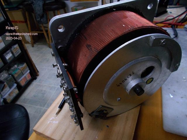 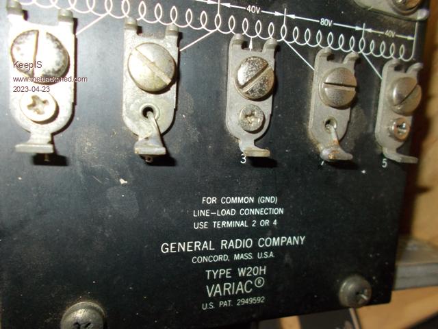 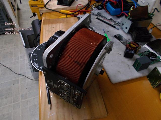 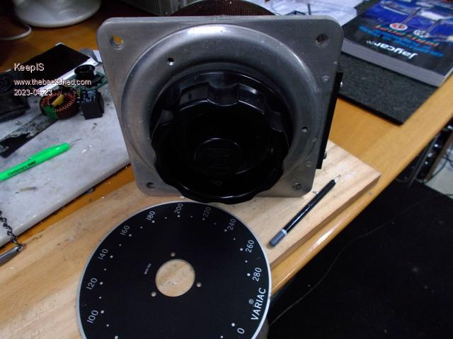 . Edited 2023-04-23 14:55 by KeepIS It's all too hard. Mike. |
||||
| analog8484 Regular Member Joined: 11/11/2021 Location: United StatesPosts: 92 |
Do you just use multiple smaller filters in parallel? That's interesting. A related topic that I have been wondering about is whether it's practical to have a pluggable transformer using Anderson SB connectors with some (3-5ft) increase in the primary side cable length. |
||||
| KeepIS Guru Joined: 13/10/2014 Location: AustraliaPosts: 1401 |
I've been going through some big grid tie inverter boards that were put aside for me and pulling out the higher power filter components and the heaviest wound toriods in those filters. I've been using our band-saw to cut the AC filter sections and HV capacitors sections out of some of the boards, because of the way they are sealed and the size of the connections, I found I couldn't remove the components without breaking some of them. the Band-Saw makes it easy to remove a complete Filter ready to be installed, and PCB blocks of paralleled Capacitors. In reality, so long as the filter can pass around 60A for a short startup period without too much resistive loss, I think it will be fine. It only needs to loaf along at 25A or less 98% of the time. I was wondering about that to, there is usually a few feet of cable in some chokes to start with, and I think the long exposed Primary may introduce a lot of extra RF / EMF radiation from what are very intense high pulse current connections. On top of that there will be some skin effect in the primary cables and connections because of the RF components generated by the primary waveforms and currents. This exaggerates any heating or loss in the cable and connections (connectors). I had to really work on the bolt, washer and EYE terminal connections in the primary to keep that heating loss to a minimum at 5kW. The two big primary connections are obvious in the Inverter cabinet photo, the secondary connections are via a heavy terminal block using ring terminals, other components are connected to the secondary by paralleled terminals connections, so nothing is disturbed when removing the transformer itself. It literally took me two minutes to remove the Transformer the other day. After rewinding the primary, another two minutes and it was back in and running. Having the back of the cabinet removable in a few seconds and a big cabinet door means every connection and component is easily accessible. . Edited 2023-04-24 13:34 by KeepIS It's all too hard. Mike. |
||||
| KeepIS Guru Joined: 13/10/2014 Location: AustraliaPosts: 1401 |
I've followed almost every Inverter build on this and other forums over the past few years. Particularly the failures and especially the unexplained failures. I was reminded of this again when reading another thread, likely totally unrelated as the talented builder is trying to get some code running, so harder to track down. But I thought I would bring this up again. Right from the start I had this nagging feeling that something was not been considered. As a result I've pondered and suggested the following before. So, for what it's worth, I wonder: We build bigger and bigger magnetically stiff toriod transformers, wound with massive cross sectional cables, then build Chokes with the same huge cable, and connect it all together with the same massive cable, this has been the norm for years in all the forums, and rightly so. Therefore, the FETs must be looking into a complete short circuit if anything in the load causes the Toriod to go into what I like to call "Flux shock" ..... because it's what I imagine and hear in the toriod sometimes. Quite often it's not even a big load, just a combination of smaller loads switching and interacting at different times, the result causes the Toriod to almost ring, sometimes quietly so you hardly notice, sometimes the pulse is so fast you could easily miss it. Since then, I have intentionally wound my Chokes with a smaller gauge cable, yes they may get a bit warm, but the way I've made them, wound single layer and lots of air flow, allows for that, and I haven't had a problem. One reason I like the 4 turn 10 Stack toriod choke in the LO side, lots of air space and still a good length of cable (almost 800mm) spread out with plenty of air over 4 turns and 36uH with big saturation limits. I know that extra cable resistance appears to go against all the effort to make the rest of the Inverter as low loss as possible, but that is not really true when you understand the reason we make the Toriod so big. In reality, I see that small resistive loss as a safety buffer between the Primary and the FETs. This extends to the total inductance. I understand that you might want that inductance to disappear (saturate) once the FETs are fully on (max power to Toriod), but I never go below 40uH or much above 75uH total inductance, along with a measured (verified) saturation current capability that extends past 550A before full saturation. I use two chokes, one in the HI and one LO side, a big 10 stack mentioned above, the second is a Hybrid choke of Ferrite E-Core and small stack Toriods. It allows the Ferrite E-Core to do it's thing at higher RF switching harmonic frequencies, the second part of the Hybrid choke is a smaller 4 stack toriod, each around 16uH for a combined 32uH. The 4 stack Toriod allows the Ferrite E-Core to run cold, silent and combined it has a higher saturation point. With a DSO and 700A current sensor, I measure 527 Amperes @ 47.8v DC pulses every 10ms for one second when starting one piece of machinery. More importantly, just switching on a Laptop charger (SMPS) can cause a DC current spike of 190A. Anything with Phase switching power control can be problematic to our inverters, more-so depending on the existing inverter load conditions. How many builders are aware of the very high transient peak input currents hidden in seemingly small switched loads connected to their inverter. Accepting, and insuring that I have this small R-LOSS built at this location is, I feel, one of the reasons I have not had a single failure. - Yet. Technically you could disagree, it's your inverter, but, I won't be changing something that can start the 25kW surge from a 3HP loaded Induction motor, and everything in between. I have it running with 4kW of mixed load, then on top of that load I switch a 19kW induction startup load, on and off 10 to 20 times an hour. . Edited 2023-05-01 13:27 by KeepIS It's all too hard. Mike. |
||||
