
|
|
Forum Index : Electronics : Hopefully? Another 48vdc-240vac Toriod Inverter build.
| Author | Message | ||||
| KeepIS Guru Joined: 13/10/2014 Location: AustraliaPosts: 1877 |
They say the Choke is for a Transformer design Inverter, but the choke looks more like a Transformer-less Inverter choke, DC->HVDC->AC. It appears to have 4 Toriod rings and is similar to the windings of Chokes in these Inverters and they also have a much higher Inductance. The toriod Choke I purchased some time ago has around 6 in hand heavy gauge wires, they are wound as a single layer winding, there is no twisting on the cores, no lumping, no overlap, completely flat side by side with some spacing that does not quite fill the full circumference of the toriod rings. Strange, unless the one you have uses very small toriods? . Edited 2023-06-01 08:32 by KeepIS NANO Inverter: Full download - Only Hex Ver 8.1Ks |
||||
| tinyt Guru Joined: 12/11/2017 Location: United StatesPosts: 441 |
I did some more reverse engineering and found out that it has 9 turns 10-in-hand (strands) of 2mm dia. copper magnet wire. There are 3 toroid rings that is probably this. Edited 2023-06-01 11:07 by tinyt |
||||
| KeepIS Guru Joined: 13/10/2014 Location: AustraliaPosts: 1877 |
If it is like the link, that would make more sense. It has a larger opening for the same diameter and thickness of toriod that I use, that means a lot less core material and therefore likely more turns for a given inductance and due to both differences, a lot lower saturation level. . NANO Inverter: Full download - Only Hex Ver 8.1Ks |
||||
Revlac Guru Joined: 31/12/2016 Location: AustraliaPosts: 1153 |
Thanks for testing all the choke testing, Mike, This is very helpful for those building there inverters. Not everyone will have or find the same Toroidal rings but its a good guideline to get something started and working. I have one of those (not expensive) little inductance capacitance meters (LC Meter) and its been handy even if its not perfect I think its worth having one for testing things like this. Running a large resistive load for a long time certainly reveals any hot connection.....done this.  And Not boring, it was good reading....all of it.   Edit I should probably check what frequency the little LC meter tests the different chokes with, probably won't mean much though. Edited 2023-06-01 19:55 by Revlac Cheers Aaron Off The Grid |
||||
| analog8484 Senior Member Joined: 11/11/2021 Location: United StatesPosts: 149 |
Is the fuse/holder ANL type? If so, I have also found them to be impractical for high (>100A) amps due to high resistance. Class T fuse/holder should work much better with high amps. |
||||
| KeepIS Guru Joined: 13/10/2014 Location: AustraliaPosts: 1877 |
This is true of course, I made a clamp sleeve and "partly" solved the resistance problem for the Cable clamping part. The Fuse connection itself was not the problem. I've decided that using any fuse in this location is not really useful in any case. Anyway, I've fitted the Sensor I mentioned. The Sensor supply is via an isolated 12v module, in keeping with the design of the inverter to stop unneeded ground problems, the connection for current trip is ready to be tested and is simple. Note: The supply drop out is around 15v Inverter DC input, and it's the first thing to power up "before" the Contactor has energized. There are no output glitches under any condition. Any fault during power up and run will trip the Drive and kill the Big Contractor and isolate the Inverter from the Batteries. A nice addition made easy by using this type of sensor is an Analogue meter showing Peak DC input. Meter FSD is 600A and it indicates the 540A startup correctly, along with most big loads, it just needs a Peak "Hold & Decay" mod to show the very fast spike from certian switched loads. . Edited 2023-06-02 09:57 by KeepIS NANO Inverter: Full download - Only Hex Ver 8.1Ks |
||||
| KeepIS Guru Joined: 13/10/2014 Location: AustraliaPosts: 1877 |
Another twist in the Choke "who done it" story. But first, I've modded the front panel to fit an analogue Meter to show Peak input current, when I'm finished it will be able to switch to show kW input as well. I'm glad I left the finishing of the cabinet until everything is set in stone. Moved the twin 15A socket to the RH side, a much better location IMHO. I didn't want to leave the AC skt off as it allows testing the inverter off load, and also makes it self contained, needing only DC input to power something. The power point moved to fit an Analogue Meter. The socket above the Meter is the same as the DSO skts. It brings the DC Current Sensor output to a location where the DSO can be plugged in with a patch lead without opening or disturbing the inverter. 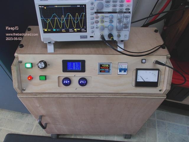 Power socket now mounted on the RH Side of the cabinet. 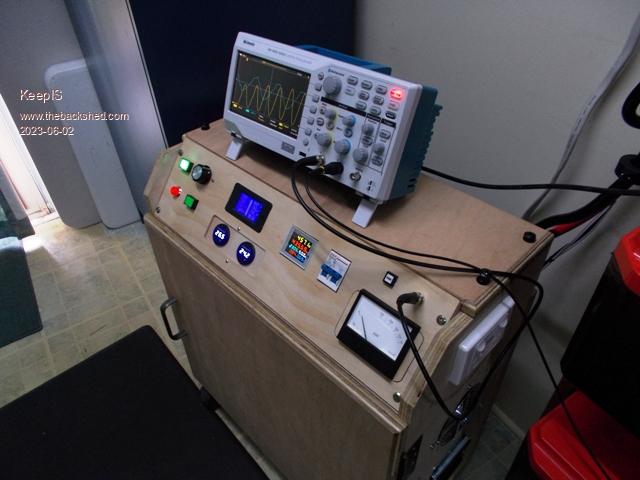 Skts above batteries are used when testing. 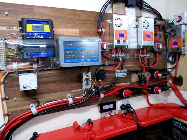 The Choke Story continues The Current drawn by the big 380A to 560A loads has dropped slightly by 5A to 15A, the Power input remains the same as the DC input voltage across the FETS is now higher and therefor less current is needed to hold 230Vac output. The Startup noise from a sustained 375A current surge lasting almost 2.5sec was very quite before, however it's now even more subdued in tone, to the point that I would hardly notice it while I'm sitting in front of the Inverter with the inverter door open eyeballing the Toriod. Who knows? on that one. Choke Inductance requirement has changed slightly? The Inverter AirCon is just audible now, and I mean just! The other bad loads are slightly more noticeable, and there is a slight 1 or 2 cycle ringing on the Step in distortion in the AC waveform, as I posted before, it's the level of ringing here that determines how loud the Toriod screams in my build. The other bad loads [Hair straightener and Heatgun on low] have a very slight buzz, it's just like the Choke inductance now needs to go another 1 or 2uH lower. Talk about getting close to the 37uH value I had, but I'm glad I'm sneaking up on it this way as this is very revealing. Trying to get a one size fits all "FOR TORIOD NOISE", is almost impossible, but for each individual inverter it's possible and worth pursuing. Especially as the multi Toriod Ring chokes are so easy to wind 4 turns through, just change the number of rings for slight inductance changes, or a turn for bigger change, or in combination with a one turn change to move the inductance up or down. When selecting a Choke for a new build, I would still start out at around 40uH [at least 300+A saturation] and then work a few uH up or down when testing a bad load, or make one by inserting a Diode in series with a heating element, like a lot of the equipment approved for use in AU have used. What Changed In my system, the R-Loss in the Fuse holder was removed, now DC input voltage only drops to 50V instead of 46v to 47v under high 300A+ current. But appeared to change the Inductance requirements slightly? Strange as some of the noisy loads are only in the 300W to 600w range, the Aircon is in the 2.2kW range. Then I remembered that not only did I strip and rebuild the DC input terminal connection plates, I also did the same to the Choke connections, and for good measure I removed and rechecked the connections to the Inverter Power board. That was enough to remove a slight R-Loss (I know because the choke connections are now cold under very high power), the change in R-Loss was enough to slightly change Inductance requirements, also this is likely the same reason for that big sustained power-up load being more subdued now. I feel it's important to remember that the noise in my inverter is only noticeable on the very worst of AC distorting loads, and most times people just avoid these loads with their inverter, but I now test with them every single time I make a change. When you get everything set up in your inverter, and have these loads making nothing more than a low hum at most, you have a benchmark to use every now and then without opening the inverter. It appears to me that any change in the wiring, chokes, toriod or drive circuity will be noticed first with these loads [buzz hum], and perhaps a sign to check the inverter, tighten connections etc. . Edited 2023-06-02 16:15 by KeepIS NANO Inverter: Full download - Only Hex Ver 8.1Ks |
||||
| analog8484 Senior Member Joined: 11/11/2021 Location: United StatesPosts: 149 |
What was the DC voltage drop with the fuse holder? Any idea how tight the terminal connections are? I had similar issues in the past and I finally got a torque wrench to consistently tighten all connections to 6 n-M unless there is specific instructions otherwise. That definitely helped. |
||||
| KeepIS Guru Joined: 13/10/2014 Location: AustraliaPosts: 1877 |
I'm sure I answered that in your quote above. This will be helpful for anyone not used to this problem and new to trials and tribulations of terminals torque, and something to be kept in mind. However, not everything in a home build system is comprised of standard purchased items with specifications. I fabricate a lot of my own terminals, connection plates, and through wall high current connection plates is one such item in use here. The advantage of 50 years of industrial machinery and electronics gives you a feel for nut, bolt and washer torque and material and dos and don’ts. Sometimes you grab a washer that appears to be the correct composition and it comes back to bite you. Time to go through the washer draws and resort them. Then there's the subject of surface flatness, and even something like a fine wire strand or wayward piece of insulation caught under the edge of a washer, obviously with higher and higher currents it's critical to get everything right. The other thing with R-Loss in connections under medium to high currents, is that it's not a constant, and it can cause random spiking of input voltage on top of load variations, some strange effects happen, especially when trying find an exact value of component to work in the system, and that system is under the influence of this problem. . NANO Inverter: Full download - Only Hex Ver 8.1Ks |
||||
| KeepIS Guru Joined: 13/10/2014 Location: AustraliaPosts: 1877 |
I finally have my Peak DC current Analogue meter calibrated. I made a precision peak detector [virtually instant attack time and slow release] with a dual setting for release time. The hard part was calibrating it to almost 600A. The meter I used was one of the two I saved in my vintage parts bin. Made by SIFAM in England, it still has the written test data and serial numbers on the sides of each. Originally marked as kW meters, I did my usual of removing the scale plate once I had enough accurate ref points, scan it in, photo shop a new scale, fit it over scale plate and done. I even include all the existing ID and type info on the new scale, basically it looks original. Made even easier as these old meters are like new. Dam it's scary seeing the pointer kiss just under 600 amps starting the Comp. It's just brilliant to be able to see at a glance the current that the FETS and Toriod are using to produce the Power to these big startup loads. One update on the Noise and waveforms: Since removing the crap Fuse holder and meticulously going over every connection to the Toriod, chokes and driver board, the startup currents has gone up slightly, I though it might drop, but the startup is even more unbelievable with the ancient 3HP compressor. Today when standing in front of the inverter filming the Meter face during calibration [don't ask], I had to ask my wife to start the compressor, "when she had just done that", I heard nothing from the inverter and the spin up of the compressor was so dam fast that it didn't ever register to my ears, I repeated it a few times during the day just to check if I'd been daydreaming, the results were exactly the same. This inverter sounds so freaking Strong, and every indication of the DSO and other measuring equipment I have connected agree with that feeling. This really is something that I though was unattainable for a home built inverter, I'm sure others have the same feeling when they get one running, especially considering the major components are salvaged from junked equipment and the rest handmade by us. It just seems so effortless now for an input surge of 27.3kW [581A peak] which includes 1.5kW of additional running loads at the time. Yes, I know  rambling on.. but it sure is fun when things work rambling on.. but it sure is fun when things work  One on the left is with my new scale. 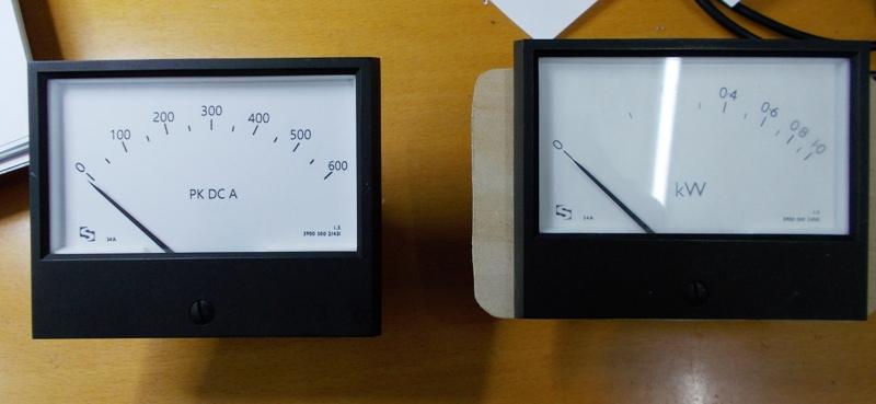 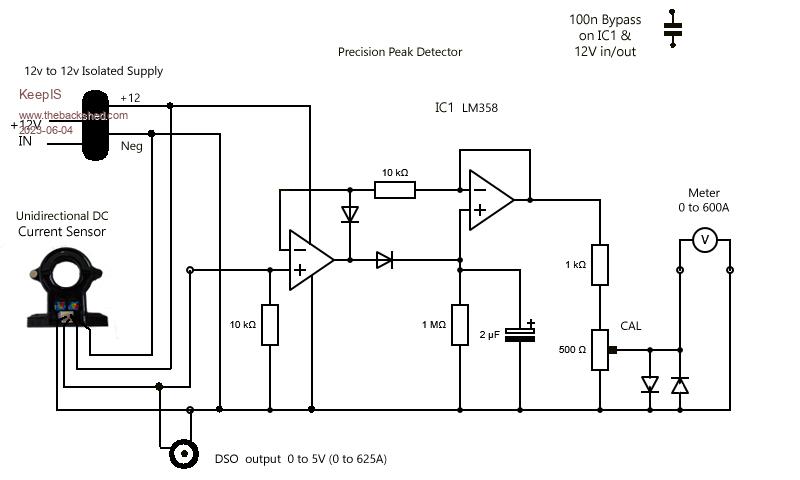 . Edited 2023-06-04 19:34 by KeepIS NANO Inverter: Full download - Only Hex Ver 8.1Ks |
||||
| analog8484 Senior Member Joined: 11/11/2021 Location: United StatesPosts: 149 |
That's curious. The random spiking happens only with changing loads? Edited 2023-06-05 04:20 by analog8484 |
||||
| analog8484 Senior Member Joined: 11/11/2021 Location: United StatesPosts: 149 |
That makes sense with reduced R-loss. I wonder if there is also noticeable improvement in overall efficiency? |
||||
| KeepIS Guru Joined: 13/10/2014 Location: AustraliaPosts: 1877 |
That's difficult to say without a dedicated real time efficiency monitor trying to detect random connector R-Loss effects, it would have to carried out with pure resistive loads across multiple current sets, not going to happen for small R-Loss. It's not a simple as that, the PD across a resistive connection depends on many variables, the rate of current change, the temperature rise in the connection, current sustained or pulsed, is the connection under physical movement from slight vibrations in the Toriod or choke with suddenly switching loads, the environmental conditions and where the inverter is located, etc. If you have ever spent time hunting down faults in very high current linear supplies you would have seen this sort of thing a lot, especially as they age. Just looking at waveforms on a DSO may not reveal much. You could of course, run the inverter up to 7 or 8 kW and use an infra red camera / sensor, or, if you have made your inverter internals easily accessible, you can just feel your way  NOTE: The Startup stall current of equipment like a big compressor varies with: 1:Environmental conditions. 2:Position of the piston in the cylinder at compressor start. 3:Pressure in the tank. 4:Heat in the pump assembly. 5:Point in the AC cycle where the Motor load is dumped across the Inverter. 6:State of Battery Charge. 7:Any variation in R-LOSS across connections when a 27kW input surge is suddenly pulled through it  You can see why measurements at the Limits of Inverter safety vary, you need to plot many readings over time to get a definitive pattern. We do what we can to make meaning out of the limited samples we have, over time a better picture starts to appear, so my interpretation can vary. These power levels are not something I would want to throw at my Inverter 30 times in a row. . Edited 2023-06-05 09:09 by KeepIS NANO Inverter: Full download - Only Hex Ver 8.1Ks |
||||
| KeepIS Guru Joined: 13/10/2014 Location: AustraliaPosts: 1877 |
For anyone interested in the Precision Peak detector: I have changed the cap from 2.2 to 4.7uF. A few tweaks to the inverter have seen the startup time of some machinery reduced. The Cap change allows me to see the current reached correctly, which in this case is almost Full scale deflection of the Meter @ 585A, just 15A shy of the 600A limit. For those who think this circuit is not accurate, it is! Right across the full scale range of the meter. These current Sensors are low cost and have a 100% repeatable response, this circuit only needs one or two cycles of 100Hz current to charge the Cap to the Peak instantaneous DC input. I'm comparing the Meter reading with a DSO capture from the Sensor output, the output is a permanent socket mounted on the Inverter control panel. I no longer need to use the DSO for Peak input checks, this meter is that good. Of course the DSO is still used for waveform analysis. For the Meter, the DC current waveform is always going to be a 100Hz DC sinewave representation of the FET current drawn to produce 50Hz AC when driving the Toriod Primary. Revised circuit: The Meter I used is 50uA FSD, but almost any meter will work, if the adjustment range is limited, a change to the 500 ohm 10 turn preset or the 1K connected to it will fix that. 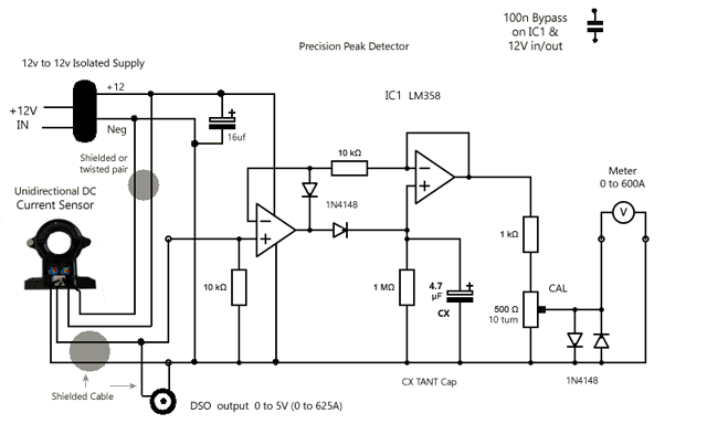 The Circuit on Vero in the Inverter. 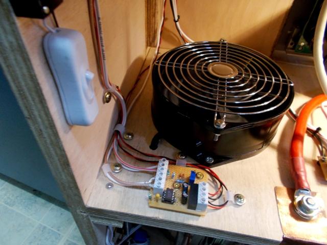 . Edited 2023-06-05 15:54 by KeepIS NANO Inverter: Full download - Only Hex Ver 8.1Ks |
||||
| KeepIS Guru Joined: 13/10/2014 Location: AustraliaPosts: 1877 |
To complete the Meter and DC input modifications, here is a picture of the current Sensor mounted in the cabinet, it replaces a big fuse holder that is really not needed here and could not handle continuous high current demands. This Hall Sensor also shuts the Inverter down if DC input is over current, much the same as the existing AC output over current trips. No waiting for a fuse to blow or a Circuit breaker to trip. Over current faults cause the big Contactor to the left of the Sensor to open the Battery feed to the inverter. [seen clearly on the last photo] That Contactor is part of the Automated Capacitor bank charge and inverter startup / shutdown functions. 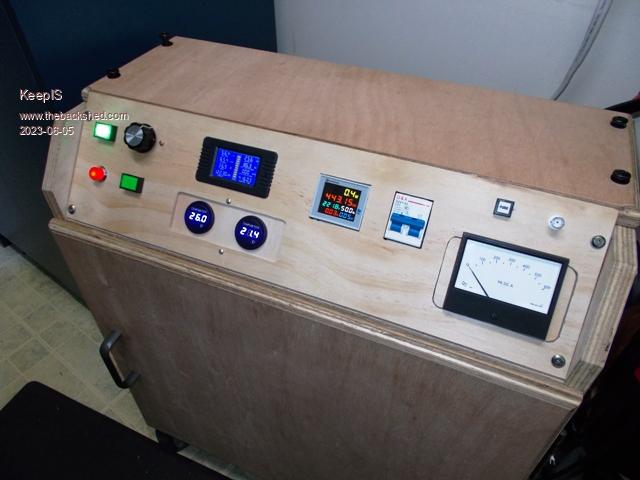 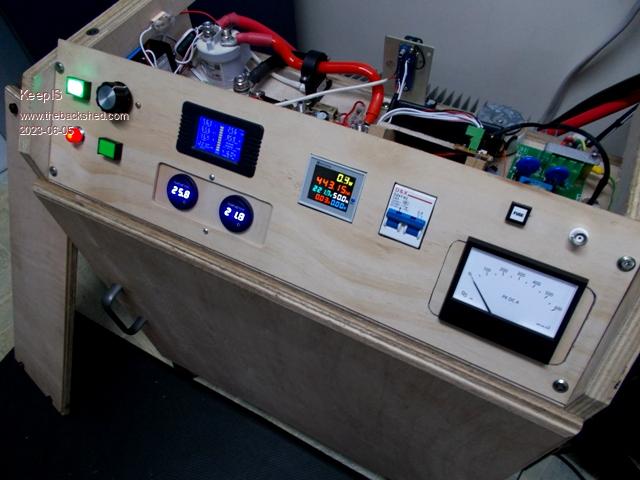 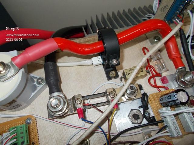 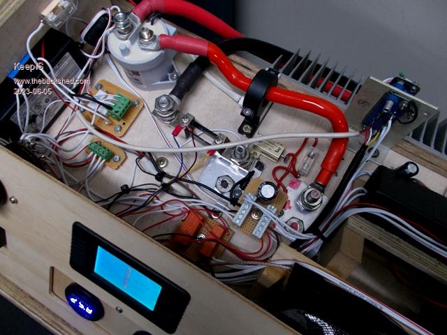 . Edited 2023-06-05 18:56 by KeepIS NANO Inverter: Full download - Only Hex Ver 8.1Ks |
||||
| tinyt Guru Joined: 12/11/2017 Location: United StatesPosts: 441 |
Nice! Can I have permission to copy your circuit? Do yo have a part number for the Hall effect sensor? Thanks. |
||||
| Murphy's friend Guru Joined: 04/10/2019 Location: AustraliaPosts: 671 |
Interesting project, thinking of building it too. Do you think it's possible to calibrate the meter without having the DSO capture facility? I looked at similar hall sensors at aliexpress but could not spot the 4 wire version you have. Where did you get yours? |
||||
| KeepIS Guru Joined: 13/10/2014 Location: AustraliaPosts: 1877 |
That's a very old circuit from way back in my Audio days, I think you will find it everywhere as there really is no other way to design it with 2 op amps, or 1 dual op amp. Most meter movements should go full scale before the two diodes across the meter start to conduct. Just some very basic protection to try and stop the coil burning out if a "brain snap" moment happens. Obviously you don't have to use an isolated supply to power it, but as I mentioned before, I'm trying to maintain earth and supply isolation to keep interference, earth loops and spikes to a minimum in this inverter. Link: D-C2T- 500A unit is the one I use in this Inverter for peak DC input. Select the option for 12V or 24V supply rail. Current consumption is <25mA. Current Sensor You really need DSO to capture the instantaneous peaks, but you could try using a CRO and your camera to video the startup up, you should be able to catch the Peak Sensor output voltage if you set the CRO correctly. But a DSO positive edge triggered and 100ms time base is hard to beat. . NANO Inverter: Full download - Only Hex Ver 8.1Ks |
||||
| KeepIS Guru Joined: 13/10/2014 Location: AustraliaPosts: 1877 |
I set a DSO up to measure the voltage across a Resistive shunt on CH1 and compare it to the Current Sensor on CH2. I wanted to see if the shunt could be used to get an accurate reading of Peak input current at high current. The shunt calibration is 75mV = 200A. I though that starting a 420A peak load through the Shunt might make it easier to get a good result above the switching noise on the DC input. It's still very difficult. Where the Hall Sensor produces a perfectly clean DC sinewave as it follows the Inverter input current, the Resistive shunt has a lot of transients and is not consistent in amplitude from cycle to cycle. The Sensor indicates 420A across the startup surge waveform, the Shunt is indicating anywhere from 430A to 560A. You might get a ball park figure from the shunt, but that's about it. If I find a way to get a consistent result I'll post it. EDIT: When starting a load drawing 570A Peak DC, the shunt displayed this 590A on the cleanest waveform cycles, but you have to understand clean in this context, but once again it was also showing values of over 700A on other cycles. Really useless, and looking at the waveform I doubt a resistive shunt even with filtering would be reliable at these high currents through DC cable. You really need the galvanic isolation provided by the HALL effect Sensor. FYI: The Precision Peak Circuit and Meter showed just over 400A on the 420A startup and hit just over 550A on the 570A start. Dam that's good. . Edited 2023-06-06 11:23 by KeepIS NANO Inverter: Full download - Only Hex Ver 8.1Ks |
||||
| Murphy's friend Guru Joined: 04/10/2019 Location: AustraliaPosts: 671 |
Thank you for that link. Forgive my limited knowledge about peak detectors but what does that meter show when there is a *steady* current flowing through the hall sensor? If it shows the value of a steady current, say 100A, then that would be accurate enough for me to deduce meter pointer positions for peak current values further up the scale. Or am I on the wrong track here? |
||||
| The Back Shed's forum code is written, and hosted, in Australia. | © JAQ Software 2025 |
