
|
|
Forum Index : Electronics : Hopefully? Another 48vdc-240vac Toriod Inverter build.
| Author | Message | ||||
| KeepIS Guru Joined: 13/10/2014 Location: AustraliaPosts: 1864 |
It's not residual magnetism. If it was and as it can easily be changed or eliminated, the change in resonance, if caused by residual magnetism would revert back to 75Hz @ 2.3uF -- but it does not. This appears to be permanent change in the Toriod, I'm not the first one to see this but I can't find anything on a search. A bit of info to clarify the testing and history of the toriod: 1: The Toriod Transformer had been confirmed resonant at 75Hz with 2.3uF for at least six months. 2: Same precision digital Generator and DSO with frequency counter and sweep have been used. 3: The CAP measured 2.3uF on a Capacitance meter. Another 2.3uF was tried, the same result. A value of 5uF was required to resonate at 75Hz. 4: The Toriod Primary and secondary leads are removed when measuring the resonance, however connecting the primary to the chokes makes no difference, and it never has, nor should it. 5: The Transformer, after starting the same huge loads and tripping at 700A peak DC input a few times when a VARIAC was turned on, still resonates at 75Hz with 5uF. 6: The Toriod O/C energized current is still the same. 7: The Idle running power is still 26.2 watts with no circulating fan and the Contactor not energized. 8: A shorted turn or other physical fault in the Toriod should change more than the resonant frequency. Therefore IMHO, it's reasonable for me to assume that residual magnetism, measurement error, previous measurement error, faulty component or physical damage is not the cause? . Edited 2023-08-21 09:18 by KeepIS NANO Inverter: Full download - Only Hex Ver 8.1Ks |
||||
| KeepIS Guru Joined: 13/10/2014 Location: AustraliaPosts: 1864 |
Once again using a differential probe across the Toriod Chokes: The HI and LO drive is symmetrical in this inverter: While monitoring the waveform across either choke, I short the other choke while the inverter is running. Note: You must not use a thin jump lead for this, use at least a 25mm "diameter" short cable. The only change is the waveform voltage doubles across monitored choke. No other changes are noted except for the expected slight increase in PWM noise on the AC output, obviously shorting one choke halves the inductance between Power Board PWM output and the Toriod transformer. EDIT: I should have included the reason why I was interested in confirming this test on the Inverter. A while back I realized that a single high current choke with some inductance left at over 300A @ 36uH to 42uH was going to be over 200mm in length. I used Sendust Toroidal Powder Core [Iron, Aluminum and Silicon] These come in various sizes and these units a quite heavy for the size as the hole in them is 26mm, others have a much larger inside diameter for the same outer dimension, so much less core area. These are 16mm High, 58mm Diameter and 26mm inside Diameter. By using two Chokes 100mm long, and each choke wound with only 4 turns through six stacked toriod rings (2 x Blue + 4 x Black rings), ended up giving me a value of 20uH and over 300A for each choke. The result is more cooling through the choke due to wide spaced turns and each choke running at half the power of one large choke. . Edited 2023-08-21 13:43 by KeepIS NANO Inverter: Full download - Only Hex Ver 8.1Ks |
||||
| nickskethisniks Guru Joined: 17/10/2017 Location: BelgiumPosts: 462 |
Thanks for sharing all your findings! |
||||
| KeepIS Guru Joined: 13/10/2014 Location: AustraliaPosts: 1864 |
 And thanks for the prompt to start using the diff probe. And thanks for the prompt to start using the diff probe.I believe it was a conversation between Poida and possibly yourself. Anyway the consensus was that at least one differential probe, even better if you could afford two, are an absolute must have for any serious waveform investigation on equipment like inverters etc. NANO Inverter: Full download - Only Hex Ver 8.1Ks |
||||
| KeepIS Guru Joined: 13/10/2014 Location: AustraliaPosts: 1864 |
A day of some serious Current tripping, I wonder if you can get high on that  I was now confident that the Inverter was back to its old self after getting the toriod back to 75Hz. I spent some time setting the AC trip point and the newly added Peak DC current input trip point. I stopped a few days ago when I looked at the Flat tops and bottoms of the DC input current waveforms - I knew something was not right. So for anyone interested, I have some screen saves from the DSO and a comparison of one of the loads when the Toriod was resonating at 119Hz. Even small loads were causing various levels of flat topping on the DC current sense output. Yellow: 240V AC out Blue: DC input Current Peak inrush current is 550A Comprising 1 second at over 530A + 2 seconds at over 430A for a total of 3 seconds before the current starts to finally fall off as the beast comes up to speed. . Below: Toriod Resonance - 119Hz - Flat top and bottom.  Below: Toriod Resonance - 75Hz  DE Motor Startup:  Below: A full startup capture. This is when I was still adjusting for the correct Current trip values. The Inverter tripped just as the load was up to speed, the "Auto Transfer Switch" changed over from Inverter AC power to Mains AC power in under 40ms.  . Edited 2023-08-21 19:27 by KeepIS NANO Inverter: Full download - Only Hex Ver 8.1Ks |
||||
| KeepIS Guru Joined: 13/10/2014 Location: AustraliaPosts: 1864 |
The Variac was switched on and off then back on, I had be sure it would trip. This peak DC input current is over 700A, the inverter tripped. The first AC disruption is the Variac load hitting the Inverter, the Inverter is tripping on the DC input in this screen capture, as the PWM is inhibited, there is some ringing (after the Current peak) as the Toriod transformer field collapses.  BELOW: This is the full screen capture from which the above Current Trip frame was taken. The Blue trace 700A peak is narrow and now very difficult to see against the Yellow AC output waveform. There is a second period of ringing around 40ms after the PWM was inhibited, this would be the ATS (auto transfer switch) removing the Toriod secondary from the various running Loads and transferring the AC line Loads back to Mains AC. This causes no issues with the Loads and all workshop machines have NVR switches (No Voltage Release) so they must be restarted manually if power is interrupted in any way.  NANO Inverter: Full download - Only Hex Ver 8.1Ks |
||||
| analog8484 Senior Member Joined: 11/11/2021 Location: United StatesPosts: 145 |
What an odd mystery. It's a bit unnerving that the transformer core can change so drastically. |
||||
| KeepIS Guru Joined: 13/10/2014 Location: AustraliaPosts: 1864 |
I feel the same, from memory they noticed a change in Transformer noise causing a noticeable growl at inverter power up or running, but not this kind of thing, maybe whoever reported these problems didn't recheck resonance. I'm even wondering about the three stack Toriods design I came up with. Each Toriod is wound to supply 33% of the AC output, so three heavy wound secondaries are series connected to produce a nominal 240vac, the 3 toriod stack has a common primary. I really don't think even a shorted turn somewhere near the start of the windings of one of the toriods could cause that overall shift, and I'm sure there would be a big current shift at idle or when testing the transformer open circuit current using a Variac, but both remain the same. I think I'm grasping at straws here though. I will be making another transformer exactly the same as this one, it will be interesting to see what value of secondary CAP is needed for resonance. Anyway, for now it is what it is, but a final thought I had was: Could the shift in resonance have happened prior to the Diode shorting and taking out a couple of FETs? could that have contributed to the failure? guess I'll never know! . Edited 2023-08-22 08:59 by KeepIS NANO Inverter: Full download - Only Hex Ver 8.1Ks |
||||
| KeepIS Guru Joined: 13/10/2014 Location: AustraliaPosts: 1864 |
FYI: I'm sick of carting a Heavy Dual Tracking Supply over to the inverter when I want to safely power it with a current limited supply for tests or adjustments, or when testing various solar build devices on the bench that require up to 60V DC and current limited from a few mA to a few A. This very small 0-60V, 0-5A 300W supply with constant current [0-5A] weighs just a couple of kg, 226mm x 82mm x 138mm. It had no trouble starting and running the Inverter and switching loads of 280W. Don't know why I never grabbed one before, I couldn't make it for the price. $100 for the 3 digit version and $114 for the 4 digit version from Amazon au. Next day delivery. I ran it for few hours powering the inverter with a 280W load and it runs almost cold, a "very quite" fan starts up with loads. The displays are quite accurate and not like the normal garbage I've tested. An idea of the size. It looks and feels like a well made unit, even the case is thick metal and the fit and finish are spot on. 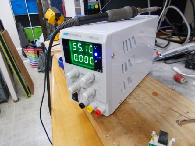 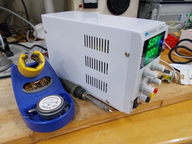  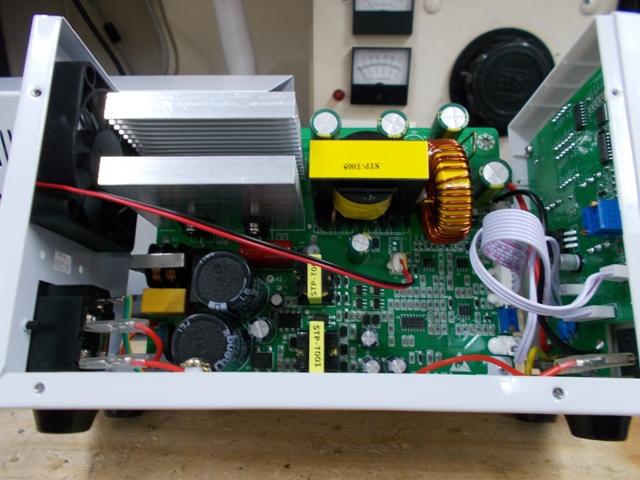 . Edited 2023-08-23 15:46 by KeepIS NANO Inverter: Full download - Only Hex Ver 8.1Ks |
||||
Revlac Guru Joined: 31/12/2016 Location: AustraliaPosts: 1151 |
Yes, they are a good little power supply I have a Wanptek 30v 10amp , would be very similar, might get the 60v version later, made a grill to go over the fan to keep the bugs out. Cheers Aaron Off The Grid |
||||
| KeepIS Guru Joined: 13/10/2014 Location: AustraliaPosts: 1864 |
I have two older supplies, what were called Laboratory Power Supplies, dual analogue 0-30V @ 3A + 5v fixed and a later Digital readout version rated at 5A, heavy and quite large but great set up in the work bench. Sure you can push some buttons and they both do series or parallel tracking, but it's a still a pain. At 60V @ 5A this little unit is ideal for Inverter testing and it can sit in the palm of my hand. These days I find if test gear is big, heavy or hard to move and setup then I tend to not use it for a quick test or mod, and that's just when I should have done so to save component destruction when I make an inevitable mistake in testing or adjustment. However, those older current limited units were the reason I never had smoke escape during all the building and experimentation I did across two inverter builds. BTW: I'm lucky that the Workshop is bug free, I do find lots of electronic ones though  . Edited 2023-08-24 08:55 by KeepIS NANO Inverter: Full download - Only Hex Ver 8.1Ks |
||||
| Pete Locke Senior Member Joined: 26/06/2013 Location: New ZealandPosts: 182 |
I went looking on Amazon for the model you pictured (Toppower?) but they don't have that listed. Although there are other breeds of the same item. 60v would be a handy addition to the bench. I bought my Rigol from Amazon. Good price, and so far as a bonus, no smoke .Cheers Pete'. Edited 2023-08-24 15:24 by Pete Locke |
||||
| KeepIS Guru Joined: 13/10/2014 Location: AustraliaPosts: 1864 |
Hi Pete: link to supply. Power Supply I was going to buy my Rigol on Amazon, but at my age and current situation I just didn't want the stress of something I really wanted going south, but so many people have had a great experience and saved quite a bit. You likely noticed the one I went for from the screen grabs, so far I'm really happy and it's a big step up from the one year old TEC, I bought that second hand from someone who found they couldn't use it, they just wanted it gone. . NANO Inverter: Full download - Only Hex Ver 8.1Ks |
||||
| Pete Locke Senior Member Joined: 26/06/2013 Location: New ZealandPosts: 182 |
Many thanks for the link Mike. Mine is on the way....fingers crossed. Cheers Pete'. |
||||
| KeepIS Guru Joined: 13/10/2014 Location: AustraliaPosts: 1864 |
NANO Inverter: Full download - Only Hex Ver 8.1Ks |
||||
| KeepIS Guru Joined: 13/10/2014 Location: AustraliaPosts: 1864 |
It appears I was wrong as the sound from the transformer had indeed changed slightly, there is a low level hum that was never there before, even with a purely resistive load. I wonder if during the process of the diode shorting and the subsequent FET failure, that the full power from the battery may have "momentarily" been dumped across the toriod primary? The Battery bank can supply over 600A at 48V, so far the change appears to be permanent. During many hours of reading old forum posts over the past week I found this gem from Mike [wiseguy]. Now, I assume that no matter what the remanence is after power off, as soon as the transformer is on and running, the resonant frequency returns to the chosen value, if it doesn't were in some serious shi!. I was aware that any remaining remanence could skew the resonant test setup and I had taken steps to mitigate that, going right back to the first build. I wonder if the change is permanent or will it revert back, I'll find the answers over time. So I guess I need to check resonance for while, until the new transformer is built and that should confirm a few things. I'll also be building a new Controller board and Power board, one way or the other I'll eventually find out what has changed. Finally, the Inverter has not had a glitch or hiccup of any kind, it's been running for the past few days at loads of 4.5kW to 5kW for up to an hour at a time and idling between 500w to 1kW most of the day. Heatsinks are always at room temperature and 3-stack toriod gets up to 36deg before a small fan kicks in for a minute or so, it never goes above that. . Edited 2023-08-25 16:42 by KeepIS NANO Inverter: Full download - Only Hex Ver 8.1Ks |
||||
| KeepIS Guru Joined: 13/10/2014 Location: AustraliaPosts: 1864 |
More info on the new controller board and the "ground plane" implementation in the inverter.  Wiseguys controller board has a PCB ground plane connection via one mounting hole on the PCB, the PCB ground plane is not a connection to the boards common 48v negative tracks or connectors. The difference in noise on the 48V positive and negative supply tracks, connections and circuits on the board is significant, it's worth every second of the time it takes to get this connection right. I was also aware the systems common negative connection to the aluminum ground plate would have to be at least 25mm copper, and no more then 150mm long to have any chance of working correctly. Testing showed a connection from the Inverters common Negative DC input mounting plate to the aluminum ground plane bolt was the most effective for reducing noise. That connection is just above the controller board where the common negative DC input bonding plate is bolted straight through from the Top switch/Interface deck of the Inverter cabinet, thus allowing the shortest direct connection to the power board and now to the controller ground plane, obviously both are mounted in the middle Deck which houses the Power and controller boards. Below: Aluminum Spacer with external Ground plate for mounting the PCB. 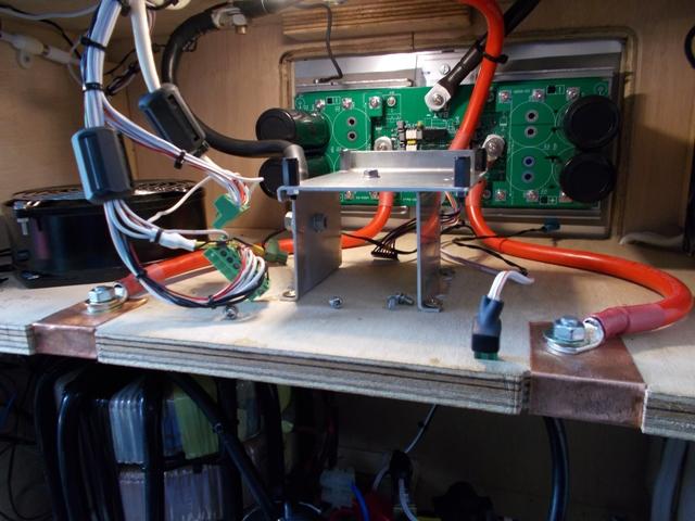  System common connection to the Ground plate is on the LH side of the Bracket.  BELOW: The New test board with those lovely big plug in connectors. Takes about 20 seconds to remove that board.  Mike [Wiseguy] pointed out that the hysteresis for the onboard dual Fan controllers would need tweaking, and I've spent a bit of time getting the values correct for my use, which is cooling the only thing that gets warm in the inverter, the Transformer. This is such a huge heavy lump of iron, temperature sensors sit between the bottom two of the three stacked toriods, and are therefore sandwiched between their secondary windings, so normal hysteresis values for heat sinks are way out, very little hysteresis is needed, like around 2 deg, it's now working very well. . NANO Inverter: Full download - Only Hex Ver 8.1Ks |
||||
| KeepIS Guru Joined: 13/10/2014 Location: AustraliaPosts: 1864 |
I decided to look at Toriod remanence: 1: A simple way to shift the Transformer flux. 2: Measure how far the transformer flux could actually shift resonance. 3: How long would the resonant shift hold in that state. Inverter off: Using a 1.5v battery momentarily flicked across the primary. I could shift the static resonance anywhere from 38Hz to 228Hz with the same CAP value, there was zero change after the shift overnight, and from previous testing it appears to stay that way indefinitely, or until a change in inverter power off conditions causes a another shift in static Toriod Flux. I use "static" here to mean measurements on an Inverter transformer that is not powered. I found the amount of shift, and direction of shift, was also influenced by the frequency of a generator connected across the secondary (via a 15K). If the frequency is below 80Hz, the shifts in resonance are to higher frequencies, if freq is above 100Hz, shifts are to low or even higher frequencies. I think of ringing in a toriod under a sudden over-current trip and an abrupt change in any DC level. I found that the only way to get back to an "even close to" consistent value of static resonance, was to connect a small AC transformer with around 7vac out across a 1K pot and connect that across the primary, bring the AC up to 7vac and then slowly back down to zero, again, one of many ways I tried to remove/reset the remanence. Using the low voltage variable AC from this setup returns the resonance to between 67Hz and 85Hz. No other method consistently worked with large shifts (36Hz to 220Hz). IMHO it proves nothing about the actual dynamic running resonance with a chosen value of CAP. Yes I know that slowly reducing PWM at shutdown has been implemented, or I could use a Variac to fully drive the transformer to 240vac out and slowly back to zero. But that does not definitely address the Dynamic running state resonance. Even when I tried to purposely resonate the transformer at 50Hz and below, trying values of Caps that would definitely have put it around that ballpark between 6uf and 12uF, I found it has zero destructive effect on the Inverter, shock loading, shock sudden load removal etc, normal ringing, normal waveforms. Moreover I seriously doubt that we can in any way be sure that we actually have this magical 75Hz static resonance that we're trying to attain in the dynamic situation of a loaded running Inverter. To this end, I'm quite happy to sacrifice my inverter to the 50Hz resonant demons, if I'm wrong then so be it. I'm basing my choice of CAP on the Inverter output and various dive waveforms around the Toriod, I'll use the rough calculated value (calculations based on an uncertain value of flux) as part of a "Toriod + secondary Capacitor" filter for a PWM generated AC waveform as a starting point. I still have to do more testing to verify what running conditions I need to choose for best output, that takes time. It may be just minimizing inverter noise on the AC waveform, or the cap value may have more of an effect on certain bad load conditions. Tests in the past and repeated again today show increasing the value of the CAP causes ringing on a bad load, but this is mostly confined to testing the inverter in Isolation or very lightly loaded, once connected to normal running off grid loads, the ringing is hardly affected by the change in CAP values. THD distortion increases slightly with reduced values of CAP, DUH! Again, only on a single load at the inverter, off Grid connection loading masks the slight increase. At this stage I have a chassis mounted block CAP of 3.3uf 480v~. I can no longer tell you with any degree of certainty what the static resonant frequency of the transformer actually is, nor do I care. So far I have briefly tested values from 1uF to 12uF while running off Grid loads, nothing really changes. I need to take time to look at the FET drive and Toriod input waveforms under similar conditions. I think the real choice of value will most likely be when I look at High current startup loads again as I did a few days back, I found a noticeable change in DC current waveforms with a higher value of CAP, however AC waveforms appeared to stay the same. . NANO Inverter: Full download - Only Hex Ver 8.1Ks |
||||
| Murphy's friend Guru Joined: 04/10/2019 Location: AustraliaPosts: 671 |
Very interesting results Mike. Too bad they are with a 3 stack toroid with 3 secondaries in series. I doubt anybody else uses that set up so those (like myself) who stacked two identical cores and wound the secondary & primary over both might have a different result with regard to resonance changes from sudden big load applications. While I do not have the equipment to test what you are doing, I have not seen anything objectionable on the AC waveform of my 6KW inverter. It runs fine and now silent, thanks to your suggestion of using toroidal choke cores. It does not complain (no grunt or howl) if I back charge 2KW into the battery bank. That 75Hz thing we got from warpspeeds posts, who is the guru in all things about transformers, chokes, etc. Unfortunately, he no longer posts here due banishment from our administrator. I might send him an email to see if he has any thoughts on this resonance mystery. |
||||
| KeepIS Guru Joined: 13/10/2014 Location: AustraliaPosts: 1864 |
Thanks for feedback Klaus. In the early days with the china inverter, this was not apparent with this same transformer, but powering it down was a little different then. I now doubt it's the transformer, the only contributing factor I can think of with regards to my transformer design is the ratio of residual flux density to maximum flux density. That might possibly come about with physically stacking 3 big cores, but that would apply to anyone who does that. Having one common primary with 3 heavy wound single layer secondaries should not really be a factor. The residual flux causing a change in resonance [inductance] after power off has been reported before and also by wiseguy. I showed how simple it was to make big changes with just a 1.5v pulse, this only served to highlight to me how fickle it might be to attempt to get a static resonance to hold in a powerful running inverter. I seriously doubt that the toriod inductance stays exactly where it was in a simple static resonance test once it's powered and running, let alone under a complex load. Now it may well return to roughly the same value at power off and still pass a static verification of resonance in a given inverter, again I doubt that carries across to a dynamic operating state. For myself, I am no longer concerned about static resonance, I certainly don't expect anyone else to follow my thoughts on this subject, just putting it out there. FYI I just received my order of 70 HY5608W FETS -- Hint --  BTW. I'm glad to hear you have the inverters running so well again. . NANO Inverter: Full download - Only Hex Ver 8.1Ks |
||||
| The Back Shed's forum code is written, and hosted, in Australia. | © JAQ Software 2025 |
